INSTALLATION & SERVICE MANUAL MODEL QST 4000 IMI CORNELIUS FOODSERVICE GROUP One Cornelius Place Anoka, MN 55303 Tel: 1-888-248-5568 / 630-539-5050 Fax: 1-800-344-3801 / 630-539-6960 Part No. 720506904 Rev.
Table of Contents UNIT SPECIFICATIONS ...................................................................................... 1 Installation ........................................................................................................... 2 Receiving ........................................................................................ 2 Unpacking ....................................................................................... 2 Counter Location ............................................
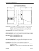
Quest Installation and Service Manual UNIT SPECIFICATIONS Nameplate Data: Model QST 4000, 115 VAC, 4.5 amps, 1 phase 60 hertz, 6.25 oz. (177g) R-134a refrigerant. Test press: High side 400 psi (27.6 bar). Low side 100 psi (6.9 bar). Model QST 4000, 230VAC, 3 amps, 1 phase 50 hertz, 6.25 oz. (177g) R-134a refrigerant. Test press: High side 400 psi (27.6 bar. Low side 100 psi (6.9 bar). Concentrate Storage: Four 0.8 gallon (3.0 liter) disposable bottles. Clearance Recommended: 12” (30.
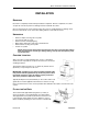
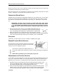
Quest Installation and Service Manual INSTALLATION RECEIVING Each unit is completely tested and inspected before shipment. At time of shipment, the carrier accepts the unit and any claim for damage must be made with the carrier. Upon receiving from the carrier, please inspect the carton for visible damage. If damage exists, have the carrier make a note on the bill of lading and file a claim with the carrier. UNPACKING • • • • • • Remove staples securing carton to pallet. Lift carton up and off of unit.
Quest Installation and Service Manual Slowly open the water shut off valve and fill the ice bath until water trickles from the overflow. This is the quickest and easiest way to fill the ice bath. Once the ice bath is full, store the fill tube in the vertically recessed holder. The fill tube can now be used as a “sight glass” to monitor the water level in the ice bath. CONNECTING WATER SUPPLY The QST series Juice Dispenser is designed to dispense juice at a high flow rate.
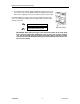
Quest Installation and Service Manual 3. After programming all the drink sizes, press and release the “cancel/pour” switch to return the Portion Control to the operational mode. The blinking REFILL light will go out. If at a future date it is decided to change the portion size of the drinks, the individual sizes can be adjusted by the above procedure. It is not necessary to reprogram every size. Additionally the portion control has full memory retention in case of a power failure.
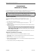
Quest Installation and Service Manual CONCENTRATE HANDLING & LOADING It is recommended that the concentrate be thawed in a refrigerated 35°F-40°F (1.6°C-4.4°C) compartment for a minimum of 48 hours prior to loading into the Quest Juice Dispenser. WARNING: Concentrate must be completely thawed and within the temperature range of 35°F-40°F (1.6°C-4.4°C) prior to loading. Failing to supply concentrate inside the recommended temperature range, especially below 35°F (1.
Quest Installation and Service Manual BRIXING PROCEDURE NOTE: If concentrate is not properly thawed, it will adversely affect the amount of concentrate dispensed. Thawed product should be between 35°F/1.6°C to 40°F/ 4.4°C. SUPPLIES • • • • • • 1-Small 12 oz. cup (354.8 ml) 1-Large 21 oz. cup (621.1 ml) 1-Straw Paper Toweling 1-Thermometer 1-Refractometer Your will also need a flat blade screwdriver to turn a screw if brix adjustments are required.
Quest Installation and Service Manual 5. To change the brix setting, simply readjust the water flow rate. Located on each of the valve assemblies inside the refrigerated compartment are the adjusting screws for the water flow rate (one per valve). If the brix reading is too high or low, rotate the appropriate water flow control according to the diagram below. Repeat steps 1-5 until the brix setting is achieved.
Quest Installation and Service Manual PLANNED MAINTENANCE SCHEDULE DAILY Flush System: 1. Move Dispense/Flush levers located on the platform assembly in the refrigerated cabinet to the “Flush” position. Place an empty cup on the drip tray below each dispense nozzle. 2. Close the door and depress each dispense button for 2-3 seconds or until clear water flows from each dispense nozzle. 3. Return the Dispense/Flush levers to the “Dispense” position. 4.
Quest Installation and Service Manual 4. Fill a clean empty concentrate container with one quart of extremely hot tap water, approximately 140°F (60°C) and place into unit. Dispense all of the hot water into a large container. Repeat for the remaining dispense valves. 5. Remove the mixing chambers, nozzles, and static mixers. Rinse in hot water to remove excess pulp and concentrate. 6.
Quest Installation and Service Manual Check and Top-Off Water Ice Bath: 1. Remove the drip tray and lower splash panel. 2. If the Ice bath level is below the “Full” indicator, top it off with water. Refer to the Filling the Ice Bath procedure in the Installation section of this manual. ANNUALLY Replace Pump Tubing: A replacement pump tubing kit, part#45098, is available. The kit consists of one pre-cut length of pump tubing, two white plastic hose clamps, and instructions.
Quest Installation and Service Manual 5. Remove the old pump tube from the pump body. If the roller assembly comes out with the tubing, place it back into the pump housing being sure to align the roller assembly shaft keyway to the motor shaft so that the two interlock. 6. Firmly press the new hose into the pump body around the roller assembly, being sure to keep the protruding ends even with each other. 7.
Quest Installation and Service Manual TROUBLE-SHOOTING GUIDE The following pages contain trouble-shooting information intended to aid an experienced service person in diagnosing operational problems that may occur. For further assistance, contact the IMI Cornelius Technical Services department at 1-888-248-5568 (630-539-6850 outside the United States) between the hours of 7:30A.M. and 5:00P.M. Central Standard Time.
Quest Installation and Service Manual PROBLEM PROBABLE CAUSE No water dis• pensed, concentrate only (continued) • Disassemble and clean solenoid. Replace if necessary. • Main water solenoid/strainer • located at the rear of dispenser is clogged, binding or defective Remove and clean strainer. Confirm 28VDC is present at solenoid during dispense. Confirm solenoid coil is not open. Disassemble and clean solenoid.
Quest Installation and Service Manual PROBLEM Warm Drink PROBABLE CAUSE REMEDY • Ambient air around dispenser is too warm • Excessive demand on dispenser • Add water pre-cooler or second dispenser • Dirty condenser coil • Clean condenser coil • Inoperative condenser fan • Replace condenser fan motor • Defective Ice Bank Control • Test and replace if necessary • Loss of refrigerant charge due to • leak in system Repair leak and recharge system Water continuous- • ly drips from nozzle
Quest Installation and Service Manual PROBLEM PROBABLE CAUSE Machine contin- • ues to dispense after dispense button is released or dispenses without operator input • 720506904 Push button or portion control pad stuck in on position REMEDY • Disconnect the wire harness from the rear of the portion control and close the door. If unit does not dispense on its own the dispense control board is bad (stuck on) Relay on voltage regulator board • (VRB) stuck on.
Quest Installation and Service Manual DIAGRAMS AND FINAL ASSEMBLIES System Wiring Diagram Revision B - 16 - 720506904
Quest Installation and Service Manual Main Electrical Box Wiring Diagram 720506904 - 17 - Revision B
Quest Installation and Service Manual Final Assembly P/N 721544101 (115VAC) Item Number Part Number Description 1 720500204 Rear Panel 2 720500301 Right Side Panel 3 720500302 Left Side Panel 4 720500504 Splash Panel 5 720500014 Grill, Drip Tray 6 720500104 Drip Tray 7 720505204 Cabinet Assembly (115VAC) 8 720500804 Refrigeration Chassis Assembly (115VAC) 9 720702702 Pin, Threaded Hinge 10 720401301 Merchandiser, Generic Graphics 11 720703402 Hinge, Bracket Assembly 12 7
Quest Installation and Service Manual Final Assembly P/N 721544102 (230VAC) Item Number Part Number Description 1 720500204 Rear Panel 2 720500301 Right Side Panel 3 720500302 Left Side Panel 4 720500504 Splash Panel 5 720500014 Grill, Drip Tray 6 720500104 Drip Tray 7 720505205 Cabinet Assembly (230VAC) 8 720500805 Refrigeration Chassis Assembly (230VAC) 9 720702702 Pin, Threaded Hinge 10 720401301 Merchandiser, Generic Graphics 11 720703402 Hinge, Bracket Assembly 12 7
Quest Installation and Service Manual Final Assembly P/N 721544101 (115VAC) P/N 721544102 (230VAC) Revision B - 20 - 720506904
Quest Installation and Service Manual Refrigeration Chassis Assembly P/N 720500804 (115VAC) Item Number Part Number 720506904 Description 1 720501304 Frame Assembly, Refrigeration (115VAC) 2 720500904 Foamed Water Bath Tank Assembly 3 720504004 Tank Cover Assembly (115VAC) 4 0702609 Screw, #8-32 BHMS, 3/4” Lg.
Quest Installation and Service Manual Refrigeration Chassis Assembly P/N 720500805 (230VAC) Item Number Part Number Revision B Description 1 720501305 Frame Assembly, Refrigeration (230VAC) 2 720500904 Foamed Water Bath Tank Assembly 3 720504005 Tank Cover Assembly (230VAC) 4 0702609 Screw, #8-32 BHMS, 3/4” Lg.
Quest Installation and Service Manual Refrigeration Frame Assembly P/N 720501304 (115VAC) Item Number Part Number Description 1 N/A 2 N/A 3 08474 Spring Clip 4 9649 Washer, Compressor Mount 5 12107 Sleeve, Compressor Mount 6 N/A 7 45073 Dryer-Solid Core, R-134a 8 48456 Tubing, 1/4” X 3/8” Premier Python 10 400276 Rivet 11 3110001 Fastener-Rivnut, #8-32 12 7221320 Bushing-Strain Relief 13 45091001 Valve, Water Solenoid, 24V 14 440000904 Probe, Ice Bank 15 560003705 Co
Quest Installation and Service Manual Refrigeration Frame Assembly P/N 720501305 (230VAC) Item Number Part Number Description 1 N/A 2 N/A 3 08474 Spring Clip 4 9649 Washer, Compressor Mount 5 12107 Sleeve, Compressor Mount 6 N/A 7 45073 Dryer-Solid Core, R-134a 8 48456 Tubing, 1/4” X 3/8” Premier Python 9 89099 Gasket, Foam-Tape 31.
Quest Installation and Service Manual P/N 720501304 (115VAC) P/N 72051305 (230VAC) 720506904 - 25 - Revision B
Quest Installation and Service Manual Tank Cover Assembly P/N 720504004 (115VAC) Item Number Part Number Description 1 720522001 Rear Support, Electrical Box 2 720509904 Bracket, Transformer 3 720521101 Bracket, Ice Bank Control 4 720509225 Split Grommet 5 720509224 Grommet 6 720509222 Grommet 7 720508104 Tank Deck Insulation 8 720504304 Electrical Box Assembly 9 720503404 Deck, Refrigeration 10 720502800 Agitator Assembly (115VAC) 12 720500795 Transformer (115VAC) 13 44
Quest Installation and Service Manual Tank Cover Assembly P/N 720504005 (230VAC) Item Number Part Number Description 1 720522001 Rear Support, Electrical Box 2 720509904 Bracket, Transformer 3 720521101 Bracket, Ice Bank Control 4 720509225 Split Grommet 5 720509224 Grommet 6 720509222 Grommet 7 720508104 Tank Deck Insulation 8 720504304 Electrical Box Assembly 9 720503404 Deck, Refrigeration 10 720502803 Agitator Assembly (230VAC) 12 720500794 Transformer (230VAC) 13 44
Quest Installation and Service Manual Tank Cover Assembly P/N 720504004 (115VAC) P/N 720504005 (230VAC) Revision B - 28 - 720506904
Quest Installation and Service Manual Cabinet Assembly P/N 720505204 (115VAC) Item Number 720506904 Part Number Description 1 45051 Stud-Latch #10-32 2 720505404 Liner Assembly, Quest 4000 3 720506104 Fan Motor (115VAC) 4 720506304 Rear Cabinet Panel, Quest 4000 5 3110001 Fastener, Rivnut, #8-32 6 720506204 Water Coil, Quest 4000 7 720519801 Bracket, Cabinet Harness 8 723232 Insert, Expansion, #10-32 9 720200206 Fitting, Insert 3/8” NPTM Quest 4000 10 720506106 Fan Guard 11
Quest Installation and Service Manual Cabinet Assembly P/N 720505205 (230VAC) Item Number Revision B Part Number Description 1 45051 Stud-Latch #10-32 2 720505404 Liner Assembly, Quest 4000 3 720506105 Fan Motor (230VAC) 4 720506304 Rear Cabinet Panel, Quest 4000 5 3110001 Fastener, Rivnut, #8-32 6 720506204 Water Coil, Quest 4000 7 720519801 Bracket, Cabinet Harness 8 723232 Insert, Expansion, #10-32 9 720200206 Fitting, Insert 3/8” NPTM Quest 4000 10 720506106 Fan Guard 1
Quest Installation and Service Manual Door Assembly P/N 720500704 Item Number Part Number Description 1 720500725 Rear Door Assembly 2 720500707 Light Panel Assembly * 31314 Fluorescent Bulb * 45433 Lamp Holder * 720511606 Ballast Board 3 720500710 Molded Gasket 4 720500780 Latch Button Assembly * Key 5 45432 Rocker Switch, Sealed 6 720500765 Bottom Hinge Plate 7 720500764 Top Hinge Plate 8 400276 Rivet 9 0704101 Screw, #8-32 X 3/8” Lg.
Quest Installation and Service Manual Door Assembly P/N 720500704 (Rev.
Quest Installation and Service Manual Lower Door Panel Assembly - Push Button P/N 720508704 Item Number Part Number Description 1 720508502 Bezel, Push Button 2* 720508601 Overlay “Push” 3 07301029 Nylon Flat Washer, 0.312” OD X 0.
Quest Installation and Service Manual Platform Assembly P/N 720500039 Item Number Part Number Description 1 77052102 Fitting, Elbow, 90 deg, 1/4” Barb 2 720506702 Bracket, Valve Mount, Quest 3 771000306 Fitting, 3.8”, 90 deg. Barb, 1.3” long 4 720509111 Tube, 2.25” Straight Plastic 5 720509114 Tube, 3.5” Long, Radius 6 48114004 Clamp-Ear, 105 (.413/.346) 7 48114002 Clamp-Ear, 170 (.669/.571) 8 720509304 Manifold, Water S.S.
Quest Installation and Service Manual Platform Assembly P/N 720500039 720506904 - 35 - Revision B
Quest Installation and Service Manual Pump Assembly P/N 45185 Item Number Part Number Description 1 45016001 Pump Gear Motor 2 45728001 Rotor Assembly (Thick Wall) 3 45050 Pump & Motor Mounting Block 4 45017001 Thumb Screw, #8-32 X 3” Lg.
Quest Installation and Service Manual Bottle Adapter Assembly P/N 45026 Item Number 720506904 Part Number Description 1 45060001 Caddy Adapter, Top 2 45060002 Run & Flush Valve 3 45060003 Caddy Adapter, Bottom 4 31525062 O-Ring 0.276 OD X 0.118 ID 5 31525064 O-Ring 5/8” OD X 0.489 ID TFE/SIL 6 31525061 O-Ring 1.489” ID X 0.070” Dia. * 45026100 O-Ring Kit (includes all O-rings needed to rebuild bottle adapter) 7 07015001 Screw, #8-18 Hi-Lo, Ph.
Quest Installation and Service Manual Valve Block Assembly P/N 45508200 Item Number Part Number Description Revision B 1 45506100 Valve Block 2 45586 Hold Down Washer 3 49612 Valve Port, Water 4 18071 Armature Seat, Water, FFV 5 7215323 Armature, Solenoid Valve 6 71815321 Retaining Ring, 0.242 ID 7 18367 Coil Spring, SS 8 31525020 O-Ring 5/16” OD X 0.
Quest Installation and Service Manual Electrical Box Assembly P/N 720504304 Item Number Part Number Description 1 720504404 Electrical Box 2 720504504 Voltage Regulator Assembly * 45012102 Voltage Regulator Board Only (includes insulator) 3 45432001 High/Low Speed Rocker Switch 4 720504414 Cover, Electrical Box 5 45758 Label - Fuse Rating 6 59328001 Fuse, 6.25 Amp, 250VAC 7 7245059 Fuse Holder 8 0734801 Pop Rivet 9 07061003 Screw, #10 Type “F” HHWF, 3/8” Lg.
Quest Installation and Service Manual Generic Bottle Assembly P/N 720500066 1 2 3 Item Number Revision B Part Number Description 1 720531826 Lid 2 720510101 Bottle, Generic 3 45248 Cap Assembly - 40 - 720506904
Quest Installation and Service Manual RECOMMENDED SPARE PARTS LIST 115VAC Wilshire Quest Series Juice Dispenser - 115VAC (based on 10 machines) Part Number Description Qty 560003705 Condenser Fan, Motor 115VAC 1 18071 Seat, Armature - Water Valve 2 18367 Spring, Coil S/S - Water Solenoid 2 31314 Fluorescent Bulb 2 45028 Transformer, 115VAC 1 45098 Pump Tubing Kit 4 45432 Inner Door Switch 1 7215323 Armature - Water Solenoid 1 7245699 Flow Control/Bonnet Assembly 2 18070002 O-
Quest Installation and Service Manual RECOMMENDED SPARE PARTS LIST 230VAC Wilshire Quest Series Juice Dispenser - 230VAC (based on 10 machines) Part Number Description Qty 560003706 Condenser Fan, Motor 230VAC 1 18071 Seat, Armature - Water Valve 2 18367 Spring, Coil S/S - Water Solenoid 2 31314 Fluorescent Bulb 2 720500794 Transformer, 230VAC 1 45098 Pump Tubing Kit 4 45432 Inner Door Switch 1 7215323 Armature - Water Solenoid 1 7245699 Flow Control/Bonnet Assembly 2 18070002
Quest Installation and Service Manual IMI CORNELIUS INC. Certificate of Warranty ONE YEAR LIMITED BEVERAGE EQUIPMENT WARRANTY IMI Cornelius Inc. warrants to the original commercial purchaser/user, that any commercial product of its manufacture bearing the name Wilshire will be free from defect in material and/or factory workmanship, and that if properly installed, maintained, and serviced in accordance with the Service Manual furnished with the product, it will perform adequately under normal use.
Quest Installation and Service Manual The table below will be used by IMI Cornelius Inc. as a STANDARD service call guide to determine fair and reasonable labor charges for warranty repairs. Charges in excess of these rates will be subject to review and/or adjustments. The labor warranty referenced in the Certificate of Warranty in this manual applies to the replacement of the defective part. IMI Cornelius Inc.