IMI CORNELIUS INC g One Cornelius Place g Anoka, MN 55303-6234 Telephone (800) 238-3600 Facsimile (612) 422-3246 Operator’s Manual SENTRY III-A POST-MIX COOLING UNIT (R-134A Refrigerant) Part No. 312021002 December 16, 1994 Revised: December 1, 1995 Control Code A THIS DOCUMENT CONTAINS IMPORTANT INFORMATION This Manual must be read and understood before installing or operating this equipment Ó IMI CORNELIUS INC; 1994--95 PRINTED IN U.S.
TABLE OF CONTENTS Page SAFETY INFORMATION . . . . . . . . . . . . . . . . . . . . . . . . . . . . . . . . . . . . . . . . . . . . . . . . . . . . 1 RECOGNIZE SAFETY INFORMATION . . . . . . . . . . . . . . . . . . . . . . . . . . . . . . . UNDERSTAND SIGNAL WORDS . . . . . . . . . . . . . . . . . . . . . . . . . . . . . . . . . . . . 1 1 FOLLOW SAFETY INSTRUCTIONS . . . . . . . . . . . . . . . . . . . . . . . . . . . . . . . . . CO2 (CARBON DIOXIDE) WARNING . . . . . . . . . . . . . . . . . . . . . . . .
TABLE OF CONTENTS (cont’d) Page COMPRESSOR DOES NOT OPERATE. . . . . . . . . . . . . . . . . . . . . . . . . . . . . . . . . . . COMPRESSOR OPERATES CONTINUOUSLY BUT DOES NOT FORM SUFFICIENT ICE BANK. . . . . . . . . . . . . . . . . . . . . . . . . . . . . . . . . . . . . . . . . . . . . . . . WARRANTY . . . . . . . . . . . . . . . . . . . . . . . . . . . . . . . . . . . . . . . . . . . . . . . . . . . . . . . . . . . . . . 20 20 21 LIST OF FIGURES FIGURE 1. SENTRY III-A COOLING UNIT . . . . . . . . . . .
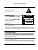
SAFETY INFORMATION Recognize Safety Information This is the safety-alert symbol. When you see this symbol on our machine or in this manual, be alert to the possibility of personal injury. Follow recommended precautions and safe operating practices. Understand Signal Words A signal word - DANGER, WARNING, OR CAUTION is used with the safety-alert symbol. DANGER identifies the most serious hazards. Safety signs with signal word DANGER or WARNING are typically near specific hazards.
THIS PAGE LEFT BLANK INTENTIONALLY 312021002 2
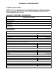
GENERAL INFORMATION CLAIMS INSTRUCTIONS Claims: In the event of shortage, notify the carrier as well as IMI Cornelius Inc. immediately. In the event of damage, notify the carrier. IMI Cornelius Inc. is not responsible for damage, occurring in transit, but will gladly render assistance necessary to pursue your claim. Merchandise must be inspected for concealed damage within 15 days of receipt.
Table 1. Design Data (cont’d) Ambient Operating Temperature 40°F to 100°F Electrical Requirements: See Unit Nameplate DROP--IN REFRIGERATION ASSEMBLY DATA Weights: No Ice Bank 103 pounds With Ice Bank 142 pounds Refrigerant Requirement (R-134A Refrigerant) See Unit Nameplate DESCRIPTION IMPORTANT: To the user of this manual - This manual is a guide for installing, operating, and maintaining this equipment.
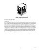
FIGURE 1. SENTRY III-A COOLING UNIT THEORY OF OPERATION (see Figure 2) A CO2 cylinder delivers carbon dioxide gas (CO2) through adjustable CO2 regulators to the soft drink tanks and also to the built--in carbonator located inside the Cooling Unit. Plain water is pumped into the carbonated water tank by the water pump and is carbonated by regulated CO2 pressure also entering the tank.
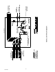
312021002 6 PYTHON LINES 1THROUGH 5 and 9 SYRUP 6 PLAIN WATER 7 CARB WATER OUT UNNUMBERED LINE IS CARB WATER RETURN BARBED CONNECTORS (9) 9-LINE PYTHON TO DISPENSING TOWER LINE LEGEND PLAIN WATER CARB WATER CO2 SYRUP CARBONATED WATER TANK SHUTOFF VALVE FIGURE 2.
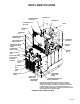
PARTS IDENTIFICATION HOOD RETAINING ACORN NUT CONTROL BOX COMPRESSOR *CONDENSER COIL AIR FILTER HOOD WATER FILL HOLE CONDENSER COIL CARBONATOR MOTOR POWER SWITCH CONDENSER FAN MOTOR CIRCULATING MOTOR POWER SWITCH CARBONATED WATER CIRCULATING PUMP MOTOR AGITATOR MOTOR COOLING UNIT POWER SWITCH SHIPPING NUT (4) UNIT ELECTRICAL BOX SYRUP INLET LINES ACCESS PANEL RETAINING SCREW (4) CO2 GAS INLET PLAIN WATER INLET OUTLET LINES LOWER ACCESS GRILLE CARBONATOR WATER PUMP MOTOR CARBONATED WATER TANK CA
THIS PAGE LEFT BLANK INTENTIONALLY 312021002 8
OWNER’S RECOMMENDED MAINTENANCE Maintenance Schedule Task D M Q A 1. Make sure CO2 cylinder regulator assembly O 1800--psi gage indicator is not in shaded (‘‘change CO2 cylinder’’) portion of dial. If so, CO2 cylinder is almost empty and must be replaced. 2. CO2 regulators should be checked for proper pres- S 3. The carbonator tank liquid level (40 to 60-ounces) S sure settings periodically and adjusted as instructed.
THIS PAGE LEFT BLANK INTENTIONALLY 312021002 10
OPERATORS INSTRUCTIONS This section covers operating controls, daily pre-operation check, adjustments, replenishing CO2 and syrup supplies, and general maintenance to be performed by the Operator on the Cooling Unit. WARNING: Disconnect electrical power from the Cooling Unit to prevent personal injury before attempting any internal maintenance. Only qualified personnel should service internal components or electrical wiring.
THIS PAGE LEFT BLANK INTENTIONALLY 312021002 12
GENERAL MAINTENANCE ADJUSTMENTS ADJUSTING CO2 REGULATORS The Operator must first check the CO2 supply to make sure it is adequate. Determine by looking at the CO2 cylinder primary CO2 regulator assembly 1800-psi gage as described in “Daily Pre-Operation Check”. Ranges for adjusting CO2 regulators are as follows: 80-psi minimum to a maximum of 125-psi for the carbonator primary CO2 regulator, 55 to 60-psi for sugar syrup tanks CO2 regulator, and 12-psi for diet syrup tank CO2 regulator.
11. Place Cooling Unit power switch in “ON”(up) position. CLEANING CONDENSER COIL (see Figure 3 CAUTION: The drop-in refrigeration assembly condenser coil and air filter must be cleaned every 30-days. Excessive accumulation of dust, lint, and grease on the air filter and coil will restrict air flow through the coil and cause refrigeration assembly to overheat. Operating refrigeration system in an overheated condition will eventually lead to refrigeration compressor failure.
1. Close empty CO2 cylinder shutoff valve, then remove empty cylinder. WARNING: To avoid personal injury and/or property damage, always secure CO2 cylinder in an upright position with a safety chain to prevent it from falling over. Should the valve become accidentally damaged or broken off, CO2 cylinder can cause personal injury. 2. Install full CO2 cylinder, the open shutoff valve. MAKE SURE CO2 CYLINDER IS POSITIONED IN UPRIGHT POSITION AND IS FASTENED WITH A SAFETY CHAIN. REPLENISHING SYRUP SUPPLY 1.
3. Using a clean syrup tank (syrup tank system) or a five-gallon container (bag-in-box system), prepare a full tank or container of liquid dishwasher detergent by using 70_F (21_C) to 100_F (38_C) potable water and 0.5 oz. (15 ml) of liquid dishwasher detergent to one gallon of potable water. Stir detergent solution to thoroughly mix the solution. 4. Syrup Tank Systems. A. Observe and note CO2 pressure setting on the syrup tanks CO2 regulator, then re-adjust CO2 regulator to 60 to 80-psi.
13. Syrup Tank Systems. Connect sanitizing solution tank, pressurized at 60 to 80-psi, into one of the syrup systems. Bag-in-Box Syrup System. Place all bag-in-box syrup containers syrup outlet tubes in container containing sanitizing solution. 14. Sanitize the syrup system and dispensing valve as follows: A. Place waste container under applicable dispensing valve. B.
Bag-in-Box Syrup System. C. Remove all bag valves from bag-in-box syrup containers outlet tubes connectors. D. Connect bag-in-box syrup containers into the syrup systems. 24. Place waste container under dispensing valves. Dispense from all dispensing valves to permit syrup to purge all potable water from the syrup systems and the dispensing valves. Continue to dispense from the dispensing valves until only syrup is dispensed from the syrup systems and valves.
TROUBLESHOOTING IMPORTANT: Only qualified personnel should service internal components or electrical wiring. WARNING: If repairs are to be made to carbonated water system, disconnect electrical power to Cooling Unit, shut off plain water and CO2 supplies, and relieve the carbonated water system pressure before proceeding. If repairs are to be made to syrup system, remove quick disconnects from applicable syrup tank, then relieve the system pressure before proceeding.
Trouble WATER PUMP CAPACITY TOO LOW.(CONT’D) Probable Cause Remedy C. Water filter clogged. C. Replace water filter cartridge as instructed. D. Inoperative water pump. D. Call Service Person TROUBLESHOOTING REFRIGERATION SYSTEM Trouble COMPRESSOR DOES NOT OPERATE. COMPRESSOR OPERATES CONTINUOUSLY BUT DOES NOT FORM SUFFICIENT ICE BANK. 312021002 Probable Cause Remedy A. Ice bank sufficient. A. Refrigeration not called for B. Electrical power to cooling unit turned off. B.
WARRANTY IMI Cornelius Inc. warrants that all equipment and parts are free from defects in material and workmanship under normal use and service. For a copy of the warranty applicable to your Cornelius, Remcor or Wilshire product, in your country, please write, fax or telephone the IMI Cornelius office nearest you. Please provide the equipment model number, serial number and the date of purchase. IMI Cornelius Offices AUSTRALIA D P.O.
IMI CORNELIUS INC.