M o b ile A c c e ss™ 1 0 0 0 /1 2 0 0 Installation and Configuration Guide Version 1.
Preface MobileAccess™ 1000/1200 MobileAccess Ltd. Vienna, Virginia Tel: +1-703-848-0200 MobileAccess Ltd. Lod, Israel Tel: +972-8-9183888 http://www.mobileaccess.com Email: sales@mobileaccess.com Copyright © 2003 MobileAccess. All rights reserved. Printed in Israel.
MobileAccess™ 1000/1200 Preface POLICY FOR WARRANTEE AND REPAIR MobileAccess tests and inspects all its products to verify their quality and reliability. MobileAccess uses every reasonable precaution to ensure that each unit meets their declared specifications before shipment. Customers should advise their incoming inspection, assembly, and test personnel about the precautions required in handling and testing our products. Many of these precautions can be found in this manual.
Preface MobileAccess™ 1000/1200 LIMITATIONS OF LIABILITIES MobileAccess's liability on any claim, of any kind, including negligence for any loss or damage arising from, connected with, or resulting from the purchase order, contract, quotation, or from the performance or breach thereof, or from the design, manufacture, sale, delivery, installation, inspection, operation or use of any equipment covered by or furnished under this contact, shall in no case exceed the purchase price of the device which gives r
MobileAccess™ 1000/1200 Preface WARNING: The MobileAccessTM system uses an optical laser for transmitting voice and data. The laser unit has the following output characteristics: - Optical output power (mW): ≤3.0 - Wavelength (nM): 1310 ± 10 WARNING: Applying power to the MobileAccess™ creates a laser energy source operating in class I as defined by IEC 60825-1, 21 CFR 1040.10 and 1040.11 except for deviations pursuant to laser notice no. 50 (July 26, 2001).
Preface MobileAccess™ 1000/1200 CERTIFICATION MobileAccess products have met the approvals of the following certifying organizations: ISO 9001 For Europe 0681 For US FCC 47 CFT part 15,22,24,90 FDA-CDRH UL For Canada RSS-118, RSS-119, RSS-133« .
MobileAccess™ 1000/1200 Preface Preface This user guide provides all the information necessary to… User Guide Organization Chapter 1. Introduction. About MobileAccess 1000/1200 . Chapter 2. Chapter 3. Chapter 4. Appendix A.
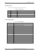
Preface MobileAccess™ 1000/1200 Revision History The revision history for this document is shown in Table 1-1. Table 1-1: Revision history Version 1.0 Date April 2003 Description Initial version.
Table of Contents Chapter 1. Introduction 1 1.1 About MobileAccess 1000/1200™ .........................................................................................................................1 1.2 1.3 1.4 1.5 Applications ...........................................................................................................................................................2 Base Unit to Remote Unit Configuration Options............................................................................
Preface MobileAccess™ 1000/1200 Appendix A. Frequently Asked Questions........................................................................................................ 31 Appendix B. : Link Measurements Form......................................................................................................... 33 Appendix C. Fiber Optic Cable Instructions ..................................................................................................... 34 Fiber Optic Cable ...............
Chapt er 1. 1.1 Introduction About MobileAccess 1000/1200™ MobileAccess™ 1000/1200 family of products provides seamless coverage for voice and data wireless services in difficult indoor environments such as those found in large corporate business buildings, airports, convention centers, hospitals and university campuses.
Introduction 1.2 MobileAccess™ 1000/1200 Applications MobileAccess™ products are designed to provide coverage for both public and private types of structures. Typical public markets include malls, airports, convention centers and hospitals; typical private markets include office buildings, business centers and campuses. (to send to JEFF) Three types of applications are very common for both markets: single-building and multi-buildings or campus type.
MobileAccess™ 1000/1200 1.3 Introduction Base Unit to Remote Unit Configuration Options The MobileAccess™ 1000/1200 system includes three basic configuration options: A) Basic configuration In the basic configuration, depicted below, the Base Unit drives a single or dual band, MobileAccess™ 1000 RHU. The dual band RHU consists of a low band service (cellular 800, iDEN, Paging, or GSM 900) and a high band service (PCS 1900 or DCS 1800).
Introduction MobileAccess™ 1000/1200 C) Using the MobileAccess 800 WLAN module to provide access to high data-rate service In the third configuration, depicted below, the WLAN module (MobileAccess™ 800) is added. The WLAN module may also be added without the MobileAccess™ 1200 unit. ModuLite 1000 ModuLite 1000 Base Unit Remote Hub Unit ModuLite 1200 Add-on Service WLAN Service Figure 5: MobileAccess 1000/1200 BU – RHU Plus Add-on Plus WLAN Configuration 1.
MobileAccess™ 1000/1200 Introduction ML-B8U Base 8 ML-B4U Base 4 Table 1-3: MobileAccess™ 1000 RHU Models MobileAccess 1000 Catalog No.
Introduction MobileAccess™ 1000/1200 ModuLite 410430 MASTER WLAN 800 RHU 1200 Base Unit Remote Hub Unit (RHU) RF Interface Unit (RIU) Downlink BTSC 1 RF in (sector #2 optional) Summed Signal BTSC 1 F/O Tx Filters and Duplexers F/O Tx #8 Uplink RF in (sector #1) BTS Service #3 F/O Tx #1 To antenna... To antenna... Uplink To antenna... F/O Tx #1 F/O Rx RF in (sector #2 optional) To antenna...
Chapt er 2. Module Description The MobileAccess™ 1000/1200 system consists of four major components: • Radio Interface Unit (RIU) • Base Units (BU) • Remote Hub Units (RHU) 1000/1200 • Controller 410/430 The number and type of modules vary in each system according to the configuration: 2.1 Radio Interface Unit (RIU) 2.1.1 General The Radio Interface Unit ensures optimal signal level between the RF source and MobileAccess 1000 Base Units.
Module Description MobileAccess™ 1000/1200 LED indicators on the RIU front panel show the status of each input RF signal on each and of the RIU power. All connections on the BTS side and on the BU side are implemented on the rear-panel. The RIU front and rear panels are described in the following section. 2.1.2 Front and Rear Panel Descriptions RIU Front Panel The RIU front panel provides all the indicators and LEDs.
MobileAccess™ 1000/1200 Module Description RIU Rear Panel The rear-panel provides all the connections on the BTS side and on the BU side as well as connections to the MobileAccess 410/430 controller and the power connection. Two types of BTS side connections are available for each BTS conditioner: non-duplexed and duplexed.
Module Description MobileAccess™ 1000/1200 During power-up, the Base Unit identifies the active connected RHUs that are connected to that Base Unit and each of the corresponding link LEDs is lit according. 2.2.2 Base Unit Front and Rear Panels The front panel contains all the optical connections while the rear panel contains all the RF connections. Front Panel The following figures shows the front panel of an eight port BU and a four port Bu. Figure 2-3.
MobileAccess™ 1000/1200 Module Description Rear Panel The Base Unit rear panel on which the BTS side (RF) connections are located is displayed by the following figure. Pair of uplink and downlink connections for interface to BTS side (all four connectors must be connected) Alarms connector Figure 2-5. Base Hub Unit Rear Panel (RF Connections) Table 2-3. MobileAccess 1000 Front Panel Indicators Connector Description Uplink output Uplink connectors to be connected on BTS side.
Module Description 2.2.3 MobileAccess™ 1000/1200 Remote Hub Unit (RHU) On the downlink, the RHU converts the optical energy received from the BU back to RF energy which is then delivered to the connected indoor antennas. On the uplink, the RHU converts the RF energy from the antennas to optical energy which is then delivered to the Base Units.
MobileAccess™ 1000/1200 2.2.3.2 Module Description MobileAccess 1200 RHU 1200 is supplied in two configurations: • MobileAccess 1200 add-on. This unit is installed on the MobileAccess™ 1000 unit (supporting this option) . RHU 1200 add-on unit enables expanding the RHU 1000 unit capabilities by an additional service. The supported band varies depending on the model of the RHU 1200 add-on unit. RHU 1200 is simply connected to the existing RHU 1000 unit. • MobileAccess 1200 standalone unit.
Module Description 2.2.4 MobileAccess™ 1000/1200 MobileAccess 410/430 Controller NOTE: This section provides general information on the MobileAccess 410/430 Controller. For detailed information onf the controller, configuration and connections refer to xxxx. The MobileAccess controller enable managing and controlling the MobileAccess system elements.
MobileAccess™ 1000/1200 Module Description Local RS232 connection (for IP address setup) Major, Minor LED Master/Slave configuration Run and Power LEDs LCD alarm display corresponding to Major and Minor LEDs Figure 2-8. MobileAccess 410 Front Panel Local RS232 connection to Laptop (RF2Litenna for Remote controller) TCP/IP connection Figure 2-9. MobileAccess 430 Front Panel 8 MobileAccess BU connections 4 Litenna BU connections Input for general purpose alarms Alarm outputs (BTS) Figure 2-10.
Chapt er 3. Installation Procedure This following installation procedure is based on the assumption that site survey and installation planning (including power requirements) have been completed: • Infrastructure preparation according to site analysis and planning: Fiber Optic, coax cable and DC cable installation, Splice the fiber optic cable according to the fiber optic infrastructure design plan.
MobileAccess™ 1000/1200 3.1 Installation Procedure General There are two types of installations: single-building and multi-building (campus) configuration. This section describes the recommended Fiber Optics and system location for both configurations. It is recommend to perform the following steps for all MobileAccess installations (both single- and multi-building). Single-building Installation In this installation, all Base Units are placed in the same location (usually in the communication room).
Installation Procedure MobileAccess™ 1000/1200 Floor n Fiber Optic Cable 2-8 Fibers MRC Floor 9 Floor 8 Splice box MRC MRC Floor 7 19" Rack PigTail Jumpers Patch panel 2-8 Fibers Splice tray Splice box MBU 12 MobileAccess 1000/1200 User’s and Installation Guide MRC Floor 2
MobileAccess™ 1000/1200 Installation Procedure Example 2: Horizontal Structure In a horizontal layout installation, a separate fiber optic cable is connected to every site location, where a site may include more than one RHU. The connection may be to a splice box or directly to the RHU (depending on the site confiugraiton).
Installation Procedure 3.2 MobileAccess™ 1000/1200 About Infrastructure Installation Note: When working with fiber optics, it is crucial to maintain a clean working environment. However, if the working environment has been tainted or if the optics connectors has not been covered, refer to appendix x for information on cleaning the fiber optic cable. ATTENTION: MobileAccess™ requires singlemode fibers with SC/APC connectors. Be sure to use only these types of fibers.
MobileAccess™ 1000/1200 3.3 Installation Procedure Power Supply for the MobileAccess™ Note: Power to the MobileAccess™ modules may be supplied by any configuration of power supplies that provide the necessary voltage and power. It is recommended to calculate the required power according to the requirements of the specific installation and then determine the configuration of the power supplies. The required DC cables will then be determined by the selected PS configuration.
Installation Procedure MobileAccess™ 1000/1200 Table 3-2: Power Supply Options Materials Model Local power supply LPS-24-1A Remote power supply (no redundancy) Remote power supply (fully redundant) Remote power supply (fully redundant) Remote power supply (fully redundant) RPS-200-N-48 RPS-150-R-48 RPS-500-R-48 RPS-1000-R-48 The example in Figure 3-2 depicts a MobileAccess™ GSM Dual Band installation with 500W/ 48VDC AC/DC converters providing a total of 0.5A power.
MobileAccess™ 1000/1200 3.
Installation Procedure MobileAccess™ 1000/1200 3.5 Connecting Each of the MobileAccess Elements 3.5.1 Base Unit Connections The Base Unit converts the RF signal from the BTS side to optic signals to be transmitted via optic fiber to the RHUs.
MobileAccess™ 1000/1200 C) Installation Procedure MobileAccess 1000 partial configuration: In this configuration the BU is driven by a passive interface instead of a BTSC. Unlike the previous configuration, the passive interface is supplied at the same time as the BU, so the passive interface is calibrated to supply the input power normally expected by the BU (as if a BTSC was connected). BTS (operator) 3.5.
Installation Procedure MobileAccess™ 1000/1200 7. On the uplink side, combine the ports and connect them to the duplexer uplink port via a 50Ω (RF 223) coax cable. Note: All other cables are male to male 50Ω. Attenuator Duplexer BTS B4U Figure 3-4: Example: One port BTS/RBS connected to 1BFU Attenuator Duplexer BTS 2way B8U 2way Figure 3-5:Example: One port BTS/RBS connected to 1 B8U . BTS/RBS/BDA Simplex Configuratoin 1.
MobileAccess™ 1000/1200 Installation Procedure Attenuator BTS B4U Figure 3-6: Example: Two port BTS/RBS connected to B4U. Attenuator 2 way BTS 2 way B8U Figure 3-7: Example: Two port BTS/RBS connected to B8U with six optic links 3.5.2.2 Connections via Radio Interface Unit (RIU) Each RIU can support up to four 8-port Base Units. The RIU can be expanded to support additional BU via the front panel connectors. Figure 3-8 shows the RIU rear panel connections.
Installation Procedure MobileAccess™ 1000/1200 RIU to Base Unit connections Connect each Base Unit to the corresponding pair of RF outputs on the RIU rear panel. Non-duplexed connections to a BTS Duplexed connections to a BTS or repeater DC power input MobileAccess 410/430 controller connection Figure 3-8. RIU Rear Panel showing the RF Connection 3.5.3 Base Unit to RHU connections 1.
MobileAccess™ 1000/1200 3.6 Installation Procedure Remote Hub Units (RHUs) 1000 1. Install splice box near RHU (refer to optic planning). 2. Connect fiber optic cable to splice box and (3/125/3000) pigtails to RHU 3. For the downlink, connect the fiber optic cable pigtails from splice box coming from the Base Unit port to the corresponding Remote Hub Unit port. 4. Connect the Remote Hub Unit to antennas according to the RF engineers design. (up to 4 antennas per RHU). 5.
Installation Procedure MobileAccess™ 1000/1200 To install the 1200 add-on unit 1. Remove all three SMA connectors. 2. Connect the Add–On unit with four screws to the installed RHU 1000. 3. Connect coax jumpers between units correspondently. 4. Connect power to the Add-On unit.
MobileAccess™ 1000/1200 3.7.2 Installation Procedure Remote Hub Unit 1200 Standalone RHU 1200 standalone unit provides high power support for a single band. The supported band varies depending on the model of the RHU 1200 standalone unit. The standalone RHU 1200 is connected to the communication center’s base unit by two fiber optic strands Figure 3-10. RHU 1000 with RHU 1200 add-on unit – wrong picture To install the 1200 standalone 1.
Installation Procedure MobileAccess™ 1000/1200 The following diagram depicts the upgraded remote site design: Optic Out1 Optic In Optic In1 Optic Out 3G port3 3G port2 B8U RHU GSM 900/1800 3G port1 Optic Out8 Optic In8 3G port1 3G port2 Add-onRHU UMTS 3G port3 Figure 3-12: Example - MobileAccess™ UMTS Ready Full Installation 3.8 Controller Connections The MobileAccess controller connections vary depending on the configuration of the site and the required monitoring capabilities.
Chapt er 4 . Adjustments Procedure This procedure is used to adjust the system to provide optimal performance. The system will be operational without this adjustment procedure; however, the system performance will be better. Adjustments can be made only after the system is fully installed. The adjustments procedures differ depending on the system topology: • With RIU • Without RIU • Main building adjustments • Remote building adjustments The adjustment procedure consists of three phases: 1.
Adjustments Procedure 28 MobileAccess™ 1000/1200 MobileAccess 1000/1200 User’s and Installation Guide
MobileAccess™ 1000/1200 4.1.2 Adjustments Procedure Downlink Adjustments The adjustment procedure is performed after the system installation is completed. The procedure requires injecting a signal equivalent to that provided by the BTS. This can be done by either using a signal generator or simply connecting the BTS.
Adjustments Procedure MobileAccess™ 1000/1200 2. Verify that the MobileAccess RS232 slide-in panel is inserted in the MobileAccess 410/430 controller and connect the laptop to on which the MCT application is installed to the RS232 front panel connector. 3. Launch the MCT application, double-click on the first BTSC element (i.e. BTSC 1) in the Topology tree, and access the Adjustments pane. 4. Select the type of adjustment (Live or Emulated signal source) and click Adjust.
Appendix A. Frequently Asked Questions 1. What are the BU and the RHU, and for what are they used for? The MobileAccess™ system consists of two modules: Base Unit and Remote Hub Unit. The Base Unit interfaces between the microcell or base station and the Remote Hub Unit (RHU). The interface is via either a composite cable or fiber optic cable.
Adjustments Procedure MobileAccess™ 1000/1200 12. What is the RF input power required at the Base Unit? The required composite RF input power at the Base Unit is between 0dBm to 7dBm, depending on the operating standard. 13. What alarms are in the system, and how can they be transmitted to a central monitoring system? The MobileAccess™ system can support 3 alarm options: Dry Contact alarms (Normally Closed), Dry Contact alarms (Normally Open) and open collector alarms.
: Link Measurements Appendix B. Form To smoothly carry out link measurements, refer to table Table 4-2: Fiber optic Cable Test Results. This table aids system evaluation and provides necessary feedback to MobileAccess. The following issues should be taken into account: • Measure the optical power for every link with an optical meter and light source, according to the number of links or RHU’s. • Measure the typical signal strength (RSSI) for every installed antenna.
Appendix C.
MobileAccess™ 1000/1200 Adjustments Procedure MobileAccess 1000/1200 User’s and Installation Guide 35
NOTE: In order to explain the testing procedures, the terms related to these tests need to be explained.
MobileAccess™ 1000/1200 Adjustments Procedure Fiber Optic Cable – Appendix D. Terms Fiber optic cable is produced in a variety of formats with different characteristics.
Adjustments Procedure • Jacket. glass. MobileAccess™ 1000/1200 The jacket covers the buffer, providing greater protection to the The fiber consists of Core and Clad. The central part of a fiber is known as the core, and the material surrounding the core is known as the clad. The clad has a lower index of refraction than the core, allowing light to be completely reflected off the surface between the core and the clad. As a result, propagated light remains entirely within the core.
MobileAccess™ 1000/1200 Adjustments Procedure Connecting Fiber Optic Cable In order to carry out a fiber optic connection a Splice and a Connector are required. • Splice. A splice consists of cutting the fiber optic cable across the cable’s diameter and combining the opening with another fiber optic cable. A splice can be carried out in the following methods: • Fusion – following the splice, the cables are warmed and the two fiber optic cables are melted together.
Optical Test Procedure Appendix E. This section describes the methods applied to test fiber optic cable’s optical insertion loss and return loss. Fiber Optic Cable Test Due to the extended distances that analog signal transmissions travel on cable, the major challenge is to determine the status of the cable. In order to determine that the cables are functioning, technical personnel need to perform optical power tests.
MobileAccess™ 1000/1200 Adjustments Procedure Test Equipment In order to perform these tests, the following equipment is necessary: • Light source (for wavelength 1310nm , 0dbm) • Optical power meter • Optical coupler (hosed and connectorized) • Fiber optic jumper • Adapter parts for the cable connectors For information about equipment suppliers, contact MobileAccess. Optical Insertion Loss Measurement Test The optical insertion loss measurement tests the attenuation of the cable.
Adjustments Procedure MobileAccess™ 1000/1200 Method #2: Single Point Test Connection description: This method assumes that there are two parallel fibers on the path to be tested. Connect fiber jumper at end of the cable being tested to another parallel cable. Connect the light source, optical power meter and optical jumper as shown in Figure 4-5. This measurement can test two cables simultaneously. Fiber optic jumper Light source Optical power meter Connector Figure 4-5: Single Point Test 1. 2. 3.
MobileAccess™ 1000/1200 Adjustments Procedure Optical Return Loss Measurement Test Connection description: Connect a light source and optical power to the inputs. If the coupler has one output, connect the tested cable to this output. If the coupler has two outputs make a pigtail at the second output.
Adjustments Procedure MobileAccess™ 1000/1200 Make pigtail. If cable is shorter than 100 meter, then verify that cable is disconnected at end. Measure the return light power (P2), connector #2. Calculating Return Loss Calculate the difference between the signals in dB. (Return loss)dB = (P2)dBm – (P3)dBm + (Lc)dB Results The following table is to be filled in by technical personnel testing the fiber optic cables.