August, 2022
File history Document Everon 6000 G2(3500) commissioning instruction manual title Document resume Edition V1.
Content Foreword .............................................................................................................................. 2 1 Operating environment ................................................................................................... 4 1.1 Computer hardware configuration requirements ............................................ 4 1.2 Computer software configuration requirements .............................................. 4 2 Overview ...............................
Foreword This manual introduces the Everon 6000 G2 commissioning instructions and relevant operating instructions WEB OMT configuration through IE7/IE8, Firefox and Chrome browsers. Since the system of this product will be constantly updated and the software will be constantly upgraded, the software version described in this manual may be different from the pictures. Therefore, the parameters, specifications, and others in this manual are subject to change without notice.
Abbreviation notes Table 2 DAS dLRU-G2-678 Distributed Antenna System Low Power Remote (20dBm) for 600, 700L/700U/700FN, 850, 2T2R MIMO (requires 1x10G SFP, ordered separately) dLRU-G2- Low Power Remote (20dBm) for AWS, PCS, WCS and 2.5GHz (194MHz), 2T2R MIMO 17192325 (requires 3x10G SFP, ordered separately) dLRU-G2-25 dLRU-G2-35 dMRU-G2-25 dMRU-G2-35 RIU-G2-25 RIU-G2-35 Low Power Remote (23dBm) for 2.
1 Operating environment 1.1 Computer hardware configuration requirements ⚫ Computer: main freq uency above 2 GHz, memory above 512 MB, display resolution : 10 24×768 above ; ⚫ With an RJ45 ne twork port; ⚫ Or with a USB port, e xternal USB to RJ45 network po rt. 1.
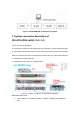
Figure 2-1 D430 WEB OMT commissioning diagram 3. System connection description of RIU+DCU+DEU+dLRU (1+1+1+1) 1) Fiber connection description The optical port connection of the system is shown in the figure. The DCU optical port OP1 is connected to the DEU OP-A port, the DCU optical port OP2 is connected to the DEU OP-B port, the DEU OP1 port is connected to the dLRU OP1 port, and the DEU OP2 port is connected to the dLRU OP2 port.
➢ ANT2 of RRU is connected to TX5/RX5, TX6/RX6, TX7/RX7 and TX8/RX8 of RIU; RIU->DCU (It request to connect RF cable and network cable between RIU and RCU): ➢ Connect the "PREV" of the RIU panel to the "to RIU" of the DCU panel with the network cable; ➢ TX1 and RX1 of RIU1 are connected to SISORX3 and SISOTX3 of DCU; ➢ TX2 and RX2 of RIU1 are connected to SISORX4 and SISOTX4 of DCU; ➢ TX3 and RX3 of RIU1 are connected to MIMORX3 and MIMOTX3 of DCU; ➢ The TX4 and RX4 of RIU2 are connected to the M
In figu re 4.1 -2 , the IP address 192 .168.8 .102 is only an example. It can be all IP add resse s excep t 101 in the sa me ne twork segmen t 192.168.8 (the defaul t IP addres s of the DAS ne twork element is 192.168 .8 .1 01). After the above operations, you can log in to WEB -OMT through the browse r, addres s: https ://1 92.168.8 .101 , de faul t accoun t: admin, defaul t pas sword: admin ; As shown in figure 4.1 -3: Figure 4.
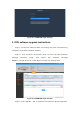
Figure 5.1-1 WEB OMT login interface 5.1 RIU software upgrade instructions Step1: connect the n etwork cable connec ting the local commissioning computer to the DCU network elemen t. Step 2 : click Functio n —Firmware—Scan to ente r the RIU so ftware package selec tion page , and imp ort the software package M52RIU_V01.00.00 .0 1.dnl o f the RIU to th e device s torage a rea . Figure 5.
and the so ftware upl oad p rogress will be displayed in real ti me unde r progress . When the p rogress pro mp t is 10 0%, i t means tha t the software package has been upl oaded. Figure 5.1-3 RIU software upgrade progressing Step4: wait fo r the so ftware upload to complete, click OK . And wait fo r the device rese t to complete (the fron t panel o f the device' s run light flashes for 1s , indica ting tha t the device re set is comple te). 5.
Figure 5.2-1dcu function interface Step3: click Upgrade - OK to pe rfo rm the software upload ope ration, and the so ftware upl oad p rogress will be displayed in real ti me unde r progress . When the p rogress pro mpt is 10 0%, i t means tha t the software package has been upl oaded. Figure 5.2-2 DCU upgrade Step4: wait fo r the so ftware upload to complete, click OK .
Figure 5.2-3 DCU software upgrade package upload completed Step5: a fte r the devi ce upgrade and reset is completed , as sho wn in figure 5 .2-4 , the software version numbe r of the DCU network element is Everon_6000_DCU_P2V01. 00 .01.41 indicates tha t the so ftware o f the DCU network element has been upg raded. Figure 5.
5.3 DEU software upgrade instructions Step1: connect the n etwork cable connec ting the local commissioning computer to the DEU network elemen t. Step2: as shown in figure 5 .3 -1 , a fte r ente ring the WEB con figuratio n page of DEU, clic k F unction —Firmware—Scan to en te r the DEU software package selec tion page , and imp ort the DEUG2_V01.00.01.27 .dn to the device sto rage area . Figure 5.3-1 DEU function Step3:click Upgrade - OK to upload the so ftware.
The software uploa d prog ress will be dis played in real time under progress . When the p rogress pro mpt is 10 0%, i t means tha t the software package has been upl oaded. Figure 5.3-2 DEU upgrade Step4: wait for the so ftware upload to co mplete, click OK in the pop up dialog box , wait fo r the device rese t to complete (the fron t p anel of the device run light flashe s as 1s , indicating tha t the device reset is c omplete), and query the so ftware version of the DEU device as DEUG2_V01.00.01 .
Figure 5.3-3 DEU software upgrade result query 5.4 dLRU software upgrade instructions Step1: connec t the n etwork cable connec ting the PC to the WEB OMT port of dLRU, and acc ess the IP address o f the device through th e browser : https://192.168.8.101, en ter the user name an d password to en te r the WEB configura tion page of dLRU. Figure 5.
software package o f dLRU, select the so ftware package o f d LRU , click Upgrade in turn , and click OK to p erform the software upgrade operation . Figure 5.4-2 dLRU upgrade After uploading the software package , w ait for the de vice re set to complete.
block diagram o f RIU, DCU and DEU in the topology display a rea , and you can dire ctly switch to the WEB con figura tion page of the co rresponding network elemen t. 6.1 RIU WEB configuration description Step1: in the topology display area o f the system, click the RIU network element bloc k diagram in the top ology display a rea to en ter the WEB configura tion pa ge of the RIU . Figure 6.
Figure 6.1-2 RIU WEB configuration page 6.2 DCU WEB configuration description Connect the ne twork cable to t he OMT po rt o f the DCU and acce ss the IP add ress o f the sys tem th rough the WEB b rowser( h ttps ://192 .16 8.8.101 ), as shown in Figure 2, the syste m will pop up whether to access th e securi ty access page. Click Accept to en ter the sys tem login page. When the sy ste m logs in for the first time, the password modification page will pop up.
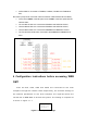
Figure 6.2-1 topology switching area Click DCU -RF config and set the band , BW, Signal Mode and RF switch of channel 5`8 as foll ows: Channel 5: Band is N 3500F, BW is 250M, S ignal Mode is TDD -NR, and RF Switch is on . Channel 6: Band is N 3500F, BW is 250M, S ignal Mode is TDD -NR, and RF switch is on . Channel 7: Band is N3500G, BW is 280 m, Signal Mode is T DD -NR, and RF switch is on . Channel 8: Band is N3500G, BW is 280 m, Signal Mode is T DD -NR, and RF switch is on .
Figure 6.2-2 DCU online interface 6.3 DEU WEB configuration description As shown in figure 6 .3 -1, click the topolog y display area on the WEB and the topology o f DEU to switch to th e WEB page of DEU fo r WEB configura tion o f DEU. Figure 6.3-1 topology switching area Click DEU -Carrier info -Add in turn to comple te the c arrier configura tion o f the c hannel of dLRU. The carrier con figuration informa tion of the channel is as follows.
ATT (DB) MIMO in tu rn. When MIMO is se t to MIMO 1 , i t mean s tha t the carrier signal outpu ts a signal fro m the ANT1 port o f dLRU, Setting MIMO to MIMO 2 means tha t the carrier signal ou tputs the signal from the ANT2 port o f dLRU. After th e configura tion is co mpleted, click Finish to complete the ca rrie r con figura ti on. Figure 6.3-2 carrier configuration page To realize the carrier output signal fro m ch annel 1 SIS O o f dLRU , the configura tion info rma tion is shown in the figure.
Figure 6.3-3 dLRU channel 1sio carrier configuration page To realize the carrier output signal fro m ch annel 3 SIS O o f dLRU , the configura tion info rma tion is shown in the figure. The con figura ti on range of UL Cen ter Freq . (MHz) and DL Cen ter Freq. (MHz) is 3700 ~39 80. In this example, 3840 M is co nfigured , and the MIMO mode is set to MIMO 1 . Figure 6.
Figure 6.3-5 dLRU channel 2 MIMO carrier configuration page T o realize the MIMO outpu t signal o f the carrie r from channel 4 of dLRU, the con figuration in formation is shown in the figure. The configura tion range o f UL Center Freq . (MHz) and DL Center Freq. (MHz) is 3700~3980 . In this example , the configu ration is 3840M, and the MIMO mode is se t to MIMO 2. Figure 6.3-6 dLRU channel 4 MIMO carrier configuration page 6.
Figure 6.