
Instruction Manual
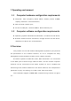
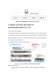
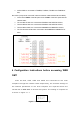
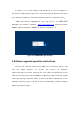
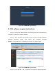

Figure 2-1 D430 WEB OMT commissioning diagram
3. System connection description of
RIU+DCU+DEU+dLRU (1+1+1+1)
1) Fiber connection description
The optical port connection of the system is shown in the figure. The DCU optical port OP1
is connected to the DEU OP-A port, the DCU optical port OP2 is connected to the DEU
OP-B port, the DEU OP1 port is connected to the dLRU OP1 port, and the DEU OP2 port
is connected to the dLRU OP2 port.
2)Equipment wiring is shown in the figure below:
Figure 3-1 system connection and commissioning diagram
Base station RRU->RIU:
➢ ANT1 of RRU is connected to TX1/RX1, TX2/RX2, TX3/RX3 and TX4/RX4 of
RIU;