
User's Manual


Corning Optical Communications
User Manual
|
Page 9
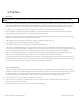
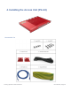
Installation Tools
The following equipment and tools are required for a successful installation:
Electric percussion drill / Screwdriver / Wrench
Torque Settings
Type
M3
M6
M10
Specified Torques
0.6Nm
5Nm
50Nm
Clearance
You must ensure the following mounting clearances for mounting within a 19” rack/cabinet:
Convection cooling:
Maintain 3U clearance between the bottom of the device and any other.
Maintain 3U clearance from the top surface of the device to the top of the rack.
FAN Cooling:
You can mount the fan between the bottom of the device and any other.
Maintain 2U clearance between the bottom of the device and any other.
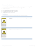
Grounding
Note: Do not use the grounding screw to connect external devices.
Requirments for grounding wires
⚫ Protective grounding conductor – should be copper with cross-section 16AWG.
⚫ Lug of the protective grounding conductor – should be copper.
⚫ Use the washer and screw pre-installed in the element. No need extra stainless steel washers.
To the devices.
⚫ Ground the device with the grounding screw located next to the power socket. See more details in the following
chapters.
⚫ Do not use the grounding screw to connect external devices.