
Installation Manual


Installation Manual
|
CMA-794-AEN
|
Page 8
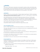
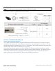
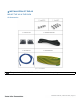
Note: The cable connector is available for 12 AWG, 14 AWG, and 16 AWG. However, the
waterproof ring must be removed when using 12 AWG and 14 AWG
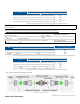
The power connector is stripped and tinned as below.
OPTICAL TRANSCEIVER MODULE
Single-Port Bidirectional SFP Transceiver
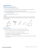
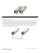
The Figure below shows a pair of single-port Bidirectional SFP transceivers. For device’s optical
connection, the transceivers of two sides must be paired -- the wavelength of one side is 1271 nm,
and the wavelength of another side is 1331 nm. Otherwise, it will fail the connection. All lower-level
devices under this port won’t be working in the system.
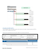
All the optical ports of all type devices have triangle LED indicators pointing to each port, which
represent the synchronization status of the upper and lower optical modules. The indicator turns to
green when optical modules are plugged into ports and synchronized. When the connection is
down, or there is no optical module in the port, the indicator remains red.