Everon™ 6000 v1.0 User Manual Corning Optical Communications www.corning.
User Manual Everon™ 6000 v1.0 User Manual Proprietary Information The information contained in this document is the sole property of Corning. The Disclosure of this information does not constitute the release of any proprietary rights therein. Permission to reproduce this information or parts disclosed herein must be obtained in writing from Corning.
User Manual v1.0 Preface Material About this Manual This manual describes how to install, use, configure and manage Corning’s Everon™ 6000 1.0 platform. It includes a description of the system end-to-end first time and on-going configuration, management and maintenance. Intended Users and Scope This manual is intended for Corning system installers, technicians and users. It is assumed that the user is familiar with the system and its units, and understands the basic functionality of the system.
User Manual v1.0 The purchaser shall not modify the software in any way. It is strictly forbidden to use this product for any purpose other than originally designated for or stipulated by Corning.
User Manual v1.0 Warranties Hardware Warranty Corning Optical Communications Wireless, Inc.
User Manual v1.0 Limitations of Liabilities Corning’s liability on any claim, of any kind, including negligence for any loss or damage arising from, connected with, or resulting from the purchase order, contract, quotation, or from the performance or breach thereof, or from the design, manufacture, sale, delivery, installation, inspection, operation or use of any equipment covered by or furnished under this contact, shall in no case exceed the purchase price of the device which gives rise to the claim.
User Manual v1.0 RF Safety To comply with FCC RF exposure compliance requirement, adhere to the following warnings: Warning! Antennas used for this product must be fixed mounted on indoor permanent structures, providing a separation distance of at least 50 cm from all persons during normal operation.
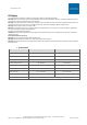
User Manual v1.0 Compliance with RF Safety Requirements: Warning! Only use a special DC supply cable with connector Warning! Always keep DC IN connectors connected during the product operation Company Certification Corning products have met the approvals of the following certifying organizations: Certification Certification No.
User Manual v1.0 Corning Restricted and Confidential Proprietary - Controlled content UM - Everon 6000 DAS - 19-DEC-2020.
User Manual v1.0 Corning Restricted and Confidential Proprietary - Controlled content UM - Everon 6000 DAS - 19-DEC-2020.
User Manual v1.0 Licensee Contact Information Industrial Boosters may only be used by FCC licensees or those given express (individualized) consent of license. Corning Optical Communications Wireless certifies all of the VARs listed as licensed installers for Corning. For the list of licensed VARs, please contact the Technical Support Team at: onesupport@corning.
User Manual v1.0 Revision History Revision Date Created by Reviewed by Changes 0.1 NOV 2020 Yoni Henya Moti Shalev First issue Aloomit Godfarb Gila Shmueli Corning Restricted and Confidential Proprietary - Controlled content UM - Everon 6000 DAS - 19-DEC-2020.
User Manual v1.0 Table of Contents 1. 2. Introduction .................................................................................................................... 16 1.1 Key Features and Capabilities ............................................................................................... 16 1.2 Terminology, Acronyms, and Abbreviations .......................................................................... 17 1.3 Applicable Documents .................................................
User Manual v1.0 2.3.10 2.4 HRU Installation ................................................................................................................... 61 2.5 Head End Unit (HEU) Installation .......................................................................................... 62 2.5.1 Verify Box Contents ....................................................................................................... 65 2.5.2 Mount the Chassis ....................................................
User Manual v1.0 6. 5.1.3 Admin Screen .............................................................................................................. 121 5.1.4 Multi-Stack Screen....................................................................................................... 132 5.1.5 Channels Screen .......................................................................................................... 133 SNMP Management ................................................................
User Manual v1.0 1. Introduction Corning Everon™ 6000 is an advanced in-building cellular service solution for small, medium and large size venues, supporting a broad range of cellular generations: 3G,4G and 5G. Corning Everon™ 6000 is based on digital distribution architecture, advanced digital processing, and channelized implementation, enabling efficient utilization of digital links.
User Manual v1.0 1.
User Manual v1.0 Abbreviation Description Remote units LRU Remote Antenna Unit: Medium Band / Low Band Picture MRU — Mid-power remote unit HRU –High-power Remote Unit NOC Network Operation Center SMV Small Medium Venues CPRI Common Public Radio Interface Corning Restricted and Confidential Proprietary - Controlled content UM - Everon 6000 DAS - 19-DEC-2020.
User Manual v1.
User Manual v1.0 Abbreviation Description UDP User Datagram Protocol Picture 1.3 Applicable Documents Table 2: References Document Name Document # NA Corning Restricted and Confidential Proprietary - Controlled content UM - Everon 6000 DAS - 19-DEC-2020.
User Manual v1.0 1.4 Everon™ 6000 1.0 Architecture Overview Corning Everon™ 6000 allows combining between Optical Network Evolution (ONE) platform, and the fully digital Corning Building Wireless System (BWS) platform, which incorporates the digital distribution units – Digital Router Unit (DRU) and remotes. Corning Restricted and Confidential Proprietary - Controlled content UM - Everon 6000 DAS - 19-DEC-2020.
User Manual v1.0 1.4.1 External Interfaces and Use Cases - Example The Everon™ 6000 system connects externally, through the Head End Unit Chassis (IHU, HEU) towards the service provider base station, over the S1 interface. Internally, the HEU IHU units are connected to the DRU units via Common Public Radio Interface (CPRI) lines. The system internal configuration and management allows user access flexibility, and is done through the DRU units, according to the needs. 1.4.1.
User Manual v1.0 1.4.1.2 MIMO Use Case The following figure shows an example of the system’s internal and external connectivity for a multiple input multiple output use case: MIMO Streams 3&4 MIMO Streams 1&2 HEU # 1 – MIMO A PSM A RIX #2 RIM 850/ SMR RIM PCS RIM PCS RIM PCS RIM RIM RIM RIM RIM AWS AWS AWS AWS AWS RIM TDD 2.5 PSM A RIM TDD 2.5 RIM 850/ SMR RIX #4 RIM PCS RIM PCS RIM PCS PSM A RIM 600 RIM 700 RIM 700 RIM 700 RIM RIM RIM RIM RIM AWS AWS AWS AWS AWS RIM TDD 2.
User Manual v1.0 1.4.2 Internal sub-units The following sections describe the system sub-units. 1.4.2.1 Head end: Radio Interface Frames (IHU/HEU) (Point of Interface) HEU IHU Radio Interface frames are modular chassis used for interface between the base stations and the Everon™ 6000. A system may be comprised of two types of Chassis: IHU (Integrated Head-end Unit) and HEU (Head End Unit).
User Manual v1.0 1.4.2.3 Remote Units • LRU Digital Remote Antenna Unit: Medium Band / Low Band The LRU is a remote antenna unit with 20 dBm per MIMO stream per band output RF power and native support of 2x2 MIMO antenna scheme. Two types of LRU are available: Low band LRU - supports 600 MHz, 700 MHz Low, 700 MHz High, FirtsNet, 800/850 MHz bands via one SFP connection. Medium Band LRU - supports EAWS, PCS, WCS and 2.5GHz TDD services via 3 SFP connections.
User Manual v1.0 • HRU – Digital High-power Remote Unit The HRU is a high power modular remote antenna unit which provides 43 dBm output RF power per service module, and native support of 2x2 MIMO antenna scheme. The HRU modular structure enables set ups of up to 8 service modules in 600/700 MHz Low/700 MHz High/FirstNet, 800/850 MHz, EAWS, PCS, WCS and 2.5GHz TDD. The HRU cooling is based on natural convection, with no fans.
User Manual v1.0 2. System Installation This chapter provides installation instructions for the system units. Refer to the specific elements required in your deployment: • Head End (HEU, HIU), see 2.5 • DRU, see 2.1 • Remote units Installation: • LRU, see 2.2 • MRU, see 2.3 • HRU, see 2.4 Note: for dimensions and specifications refer to chapter 7. 2.1 DRU Installation 2.1.1 Verify box contents The following table indicates the included and required items for installing the DRU unit.
User Manual v1.0 Item Quantity Image Part Number HARDWARE – not provided Screws Washers 4 4 SFP+ Pluggable Transceivers (hot-pluggable optical transceiver module); Support for option 8 line-rate 10.1 Gbps, single mode Optical cables Up to 900 meters LC/UPC SM DX Power cable DC: 48v AC: 100-240v Note: The image is an illustration only. Ethernet cable Grounding cable Clock 10Mhz input clock 10Mhz output clock USB to mini-USB cable Note: for technical support usage only.
User Manual v1.0 2.1.2 DRU Interfaces The following images indicate the DRU interfaces ➢ Front view AC power DC power 2 RJ45: LAN for Tech-support management Local for debug Mini USB ➢ Back view DCM (capacity) SFP ports Remote units’ SFP ports Clock Adjustable bracket LED Ground Fan Vents ➢ Side view Bracket adjustable position holes Vents Corning Restricted and Confidential Proprietary - Controlled content UM - Everon 6000 DAS - 19-DEC-2020.
User Manual v1.0 2.1.3 Mount the DRU in the 19’’ Rack 1. Determine the location of the DRU in the rack while considering additional units (e.g. power supply). 2. Position the two brackets located on the DRU sides to fit in to the rack rail. 3. Slide the DRU module into the selected slot on the 19” chassis rear. Ensure the module is flush with the chassis rear. Ensure at least 2” distance between the ventilation openings (in the rear and sides of the DRU) and any object (e.g. wall) 4.
User Manual v1.0 2.1.4.2 Power Use your selected power source (DC or AC); Connect the power-unit's cable to the DRU front panel. 2.1.4.3 Source (DCM) Connect an SFP+ Pluggable Transceiver to each source port to be used: 1. Remove the rubber stopper from the SFP connector. 2. Remove the rubber stopper from the source port (Figure 2). 3. Push the SFP connector into the DCM port, until it clicks (note that there is only one correct direction for plugging-in). 4.
User Manual v1.0 2.1.5 Verify Normal Operation ➢ SFP LED Behavior The following tables describe the DRU LEDs and the LED behaviour: LEDs Type Description and Behavior Remote unit LEDs Description: A pair of LEDs (Orange; Green) describes each port: the right pair relates to the upper slot; the left pair relates to the lower slot. Source LEDs Behaviour: Right orange LED is lit during identification and when inserting the connector.
User Manual v1.0 2.2 LRU Installation 2.2.1 Verify box Contents 1.
User Manual v1.0 Item Quantity Image Part Number RF Jumper cables PN DC Power Adapter 255760003 HARDWARE – not provided 4 screws #8 or 4mm (for attachment to ceiling) 4 SFP+ Pluggable Transceivers (hot-pluggable optical transceiver module); Support for option 8 line-rate 10.1 Gbps, single mode SOFTWARE NA Required TOOLS Phillips Screwdriver Corning Restricted and Confidential Proprietary - Controlled content UM - Everon 6000 DAS - 19-DEC-2020.
User Manual v1.0 2.2.2 LRU Interfaces SFP+ Management port Power Antenna TBD Connector Amount Antenna 2 TBD 1 Ground Type Ground Management port Power SFP+ 3 Corning Restricted and Confidential Proprietary - Controlled content UM - Everon 6000 DAS - 19-DEC-2020.
User Manual v1.0 2.2.3 Combiner Interfaces The combiner has a total of 6 input ports and 2 output ports. 2 antenna ports SFP+ CPRI ports: 1 for low band, 3 for mid-band 2 antenna ports Notes: 1. To avoid MIMO disruption, ensure the antennas are connected correctly according to the combiner labels. 2.
User Manual v1.0 ➢ Combiner Connection Interfaces Diagram Corning Restricted and Confidential Proprietary - Controlled content UM - Everon 6000 DAS - 19-DEC-2020.
User Manual v1.0 2.2.4 Fully connected system diagram The following figure shows the connections in a system that includes two units and a combiner. 2.2.5 Mount the LRU The LRU may be mounted on a wall or on a pole; single or dual. Select the configuration relevant to your deployment. 2.2.5.1 Mount on a wall Note: for the rear cases of pole mounting, refer to…TBD 1. Connect the bracket to the wall, using 4 screws, as shown in the figure below: WALL 2.
User Manual v1.0 4 screws Corning Restricted and Confidential Proprietary - Controlled content UM - Everon 6000 DAS - 19-DEC-2020.
User Manual v1.0 3. For a dual unit: • Connect the combiner to the mounted bracket using 4 screws.
User Manual v1.0 2.2.6 Connect cables For each of the units, open the cover by removing 4 screws: Unscrew and open cover Then connect the cables as follows: • Ground, see 2.2.6.1 • Power, See 2.2.6.2 • SFP+, see 2.2.6.3 Corning Restricted and Confidential Proprietary - Controlled content UM - Everon 6000 DAS - 19-DEC-2020.
User Manual v1.0 2.2.6.1 Ground Note: Ground according to local regulations The following additional (not supplied) tools and components are required for connecting the system ground: • Grounding wire - grounding wire should be sized according to local and national installation requirements. The provided grounding lug supports 14 AWG to 10 AWG stranded copper (or 12 AWG to 10 AWG solid) wire conductors. 1. Use a wire-stripping tool to remove approximately 0.4 inch (10.
User Manual v1.0 2.2.6.2 Power Connect the DC wire pair (48V) to the LRU connectors panel, via the DC power adapter (terminal block connector 2.2.6.3 SFP+ Cables Remove the rubber stopper from the SFP+ connector located in the LRU RF port Connect the SFP+ LC/UPC SM DX optic cable to the LRU optic connector.
User Manual v1.0 2.2.7 Antenna Connect the MRU male 4.3-10 Type duplexed RF “ANTENNA” port to the broadband antenna(s) using appropriate coax cables. Notes: 1. To avoid MIMO disruption, ensure the antennas are connected correctly according to the combiner labels. 2. There may be some configurations/use-cases where a combiner is not required, as there is only one type of unit (either low or mid band) Corning Restricted and Confidential Proprietary - Controlled content UM - Everon 6000 DAS - 19-DEC-2020.
User Manual v1.0 2.2.8 Combiner cables Connect the RF cables according to the figure below. Connect the Antenna cables according to the figure below. NOTE: C-Band is for future use. Mid-band Combiner in bracket Low band Combiner Notes: 1. To avoid MIMO disruption, ensure the antennas are connected correctly according to the combiner labels. 2.
User Manual v1.0 2.2.9 Verify normal operation The following table describes the LRU LED behaviour. Corning Restricted and Confidential Proprietary - Controlled content UM - Everon 6000 DAS - 19-DEC-2020.
User Manual v1.0 2.3 MRU (Digital Medium-power Remote Unit) Installation 2.3.1 Verify Box Contents 1.
User Manual v1.
User Manual v1.0 Item Description Brackets Wall mount bracket for dMRU Flavor 1 PN Image BR-dMRU-W Screws, flathead,8-32X3/8 (Quantity: 11) DC connector class 1 mating 1 Not provided AC Power Cable (AC models only) Cable, power, straight, U.S 10 A 1 ,UL, L = 1.8-2.5m ,black,110 V SFP+ Pluggable Transceivers (hot-pluggable optical transceiver module); Support for option 8 line-rate 10.1 Gbps, single mode ? Termination plug (for test port and 3.
User Manual v1.0 2.3.2 MRU Interfaces DPAM Modules FANs 3.5 GHz Units’ Release button and handle Antenna Test External Alarms Management port SFPs AC/DC Connector Warning! In the event that a PAM or the OPTM needs to be removed from the chassis, make sure to first press the release button on the module and then pull out using the handle (see Error! Reference source not found.). Any attempt to pull out the module without first releasing may cause damage.
User Manual v1.0 * MRU chassis requires 6U rack height availability * Rack nuts and screws not provided * Digital optical module & FAN are pre-installed in the chassis Corning Restricted and Confidential Proprietary - Controlled content UM - Everon 6000 DAS - 19-DEC-2020.
User Manual v1.0 2.3.3 Mount chassis in 19-in Rack Note: for dimensions and specifications refer to chapter 7 1. Before mounting the chassis: unwrap each of the PAMs, and enter each PAM to its dedicated slot inside the chassis, according to the color-codes: 2. Determine the location of the MRU in the rack while considering additional units (e.g. power supply) 3. Referring to Figure 4 secure the units’ rack ears to the rack frame as follows: a.
User Manual v1.0 2.3.4 Wall Mount This section provides instructions on how to assemble the wall-mount bracket onto the MRU and mount the assembly on the wall (belly-to-wall installation). Note: The installer is responsible for accommodating the installation to the surface type. The mounting surface shall be capable of supporting the weight of the equipment. The weight of a fully populated MRU chassis is 92.59 lbs (42 kg).
User Manual v1.0 Figure 5: Wall Mount Bracket 2. Assemble the wall-mount bracket to MRU underside Corning Restricted and Confidential Proprietary - Controlled content UM - Everon 6000 DAS - 19-DEC-2020.
User Manual v1.0 3. Insert anchors in wall, hang unit and tighten to secure Figure 6. Example of MRU Chassis wall Installation Corning Restricted and Confidential Proprietary - Controlled content UM - Everon 6000 DAS - 19-DEC-2020.
User Manual v1.0 2.3.5 Ground MRU Chassis The grounding connection is performed via a two-hole, standard barrel grounding lug located on the front of the MRU chassis (see Error! Reference source not found.) ➢ Required tools and components The following additional (not supplied) tools and components are required for connecting the system ground: • Grounding wire - grounding wire should be sized according to local and national installation requirements.
User Manual v1.0 2.3.6 Connect Fiber SFP+ Note: use SFP+ from the approved list provided by Corning. 1. Remove the rubber stopper from the source port. 2. Push the SFP+ connector into the port, until it clicks (note that there is only one correct direction for plugging-in). 3. Remove the white plug-protectors from the end of the SFP+ cable. 4. Plug the SFP+ cable into the D-MRU port until it clicks. 5.
User Manual v1.0 2.3.7 Connect Antenna NOTE: The MRU has one output, that can be split via passive splitters. 1. Connect the MRU male 4.3-10 Type duplexed RF “ANTENNA” port to the broadband antenna(s) using appropriate coax cables. Note: The test port is used for coupling; used for measuring the power without disconnecting the antenna. 2.3.8 External RF Source (3.5 GHz) The MRU includes one 4.3-10 Type RF port used for connecting to an external RF source, such as, a small cell or pico cell.
User Manual v1.0 2.3.9 Connect Power & POWER UP The MRU PSM is located on the bottom right of the chassis front. The PSM type (AC/DC) is model dependent. • Refer to section 2.4.7.1 for AC models. • Refer to section 2.4.7.2 for DC models 2.3.9.1 AC models WARNING! Approved power cable – the entire length of the power cable (or flexible cord) and the insulation must be intact. The cable must be firmly connected to both the electrical plug and the unit itself.
User Manual v1.0 2.3.9.2 DC Models DC model includes Class 1 terminal block connector: • Power input: 40-60VDC • Power consumption: 580W (maximum) • Maximum DC current consumption: 15A 1. Open PSM captive screws and pull out module from chassis. 2. Set DC input source type to “CLASS1” connector and secure PSM module back in place. See Figure 8. 3.
User Manual v1.0 2.3.10Verify Normal Operation LEDs 1. Verify that fans are operational. 2. Refer to status LEDs on the top-left of the chassis door and on each PAM to confirm normal system operation according to the following table: Table 5: MRU Chassis and DOPTM LEDs Table 6: PAM LEDs Corning Restricted and Confidential Proprietary - Controlled content UM - Everon 6000 DAS - 19-DEC-2020.
User Manual v1.0 Table 7: SFP LEDs 2.4 HRU Installation Corning Restricted and Confidential Proprietary - Controlled content UM - Everon 6000 DAS - 19-DEC-2020.
User Manual v1.0 2.5 Head End Unit (HEU) Installation The HEU chassis is supplied empty and only includes the factory assembled Fan Module (FAM) + additional modules according to the ordered PN. All other modules are ordered separately and must be installed.
User Manual v1.0 RIX ACM Up to 4 DRUs per DCM (transform RF to CPRI) ERFCxx Up to 7ACMs per 1 HCM OIX DCM DCM HCM Up to 16 remotes per DRU (combination of all remote types) Optical cable HEU # 1 – SISO PSM A RI X #2 RI M 850/ SM R RI M PCS ACM 1 PSM B RI M PCS RI M PCS RI M PCS RI M AWS RI M AWS RI M AWS RI M AWS RI M AWS RI M TD D 2.5 RI M TD D 2.
User Manual v1.0 Figure 10: Example: Installation Diagram ➢ To install the HEU, follow these steps: 1. Verify box contents, see 2.5.1 2. Mount the chassis, see 2.5.2 3. Insert the modules into the chassis, see 2.5.3 4. Connect the cables, see 2.5.4 5. Power On, see 2.5.5 6. Verify normal operation, see 2.5.6 Corning Restricted and Confidential Proprietary - Controlled content UM - Everon 6000 DAS - 19-DEC-2020.
User Manual v1.0 2.5.1 Verify Box Contents 1. Open the package and verify all elements are available according to the following table: Table 8: HEU Package Items List Item Quantity Image Part Number HARDWARE – provided in the box Headend Unit Chassis (with blank panels on RIM and one PSM slots) – includes factory installed Fan Module (FAM) in chassis rear 1 FAM Fan Module (FAM) – single unit hosting 4 fans (factory installed in chassis rear) 1 RJ45/RJ45 communication cable L=2m-2.
User Manual v1.
User Manual v1.0 2.5.2 Mount the Chassis Notes: • One IHU supports connections to up to seven Head-end units (HEUs or IHUs) in a single stack, where there in a single HCM per stack, and all the others have ACMs. • HEU chassis requires 3U rack height availability • Rack nuts and screws not provided 1.
User Manual v1.0 2.5.3 Install the Modules in the Chassis Note: For modules with ejectors (i.e. RIM, RIX and HCM/ACM) – verify that the ejectors are completely open when inserting in dedicated slot and then push in until the module clicks in to the backplane. See Figure 11: Module Captive Screws and Ejectors below, showing an example of module type captive screws and ejectors. Refer to the Figure 9: HEU Slots and Interfaces for module locations.
User Manual v1.0 2.5.4 Connect the Cables 2.5.4.1 Ground The grounding connection is performed via a two-hole, standard barrel grounding lug located on the HEU rear panel. • For use with stranded copper wire conductors • 10-14 AWG • Holes - 1/4 inch Grounding Lug (Chassis Rear) 2.5.4.
User Manual v1.0 2.5.4.3 RIX TO OIX Connections Note: Each RIX module supports connections to up to two IHU. 1. Using the appropriate length ERFC cable (according to distance of available OIX port) connect the HEU RIX module 9-Pin connector to the corresponding connector on the IHU OIX module. HEU RIX IHU OIX 2. Refer to TBD for schematic diagram of coax connections in a maximum HEU-OIU configuration of 4x4 where all HEU units are connected to all IHU units. 2.5.4.
User Manual v1.0 2.5.4.5 Management Connections Notes: • One RJ45/RJ45 management cable is provided with each headend unit (i.e. HEU/IHU). • Up to 7 ACMs are connected to a single HCM, where the connection between the units is using RJ45 cables.
User Manual v1.0 2.5.6 Verify NORNAL Operation If RF source is operational, verify that the RIM, DCM and HCM/ACM LEDs indicate normal operation Corning Restricted and Confidential Proprietary - Controlled content UM - Everon 6000 DAS - 19-DEC-2020.
User Manual v1.0 2.6 Integrated Headend Unit (IHU) Installation The IHU chassis is supplied empty and only includes the factory assembled Fan Module (FAM) + additional modules according to the ordered PN. All other modules are ordered separately and must be installed.
User Manual v1.0 ➢ Example of system connection The following figure described the optimal rack installations for a maximum 4x4 HEU-IHU configuration in shared and dedicated equipment scenarios, see Figure 10 ➢ IHU Expansion Connections TO IHU, HEU and DRU Units A single IHU supports expansion connections as follows: • To one additional IHU unit • To 7 HEU and 8 DRU ➢ To install the IHU, follow these steps: 1. Verify box contents, see 2.6.1 2. Mount the chassis, see 2.6.2 3.