
User's Manual
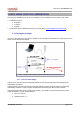
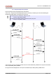
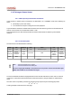

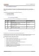
Table Of Contents
- 1. INTRODUCTION
- 2. RS232 SERIAL PROTOCOL PRESENTATION
- 3. setting the internal parameters of the wavecard
- 3.1- Configuration of the functional parameters
- 3.2- Configuration of the control parameters
- 3.2.1 - selection of the radio operating channel when FHSS is deselected
- 3.2.2 - Selection of the RF medium physical mode
- 3.2.3 - Selection of the radio board emission power
- 3.2.4 - Activation of the Wavenis RF Asic RSSI threshold autocorrection
- 3.2.5 - Selection of the serial baudrate.
- 3.2.6 - Reading the firmware version of the WaveCard
- 3.2.7 - Reading the RSSI level (Received Signal Strengh Indicator)
- 3.2.8 - TEST Mode
- 4. SERVICE COMMANDS
- 5. COMMUNICATION MODES
- 5.1- 'Frame Exchange’ Mode
- 5.2- 'Message’ Mode
- 5.3- ’Polling’ Mode
- 5.4- ’Broadcast’ mode
- 5.4.1 - Configuration of the parameters relating to the 'Broadcast' mode
- 5.4.2 - 'BroadCast' mode without waiting for a response
- 5.4.3 - 'BroadCast' mode with waiting for responses
- 5.4.4 - Format of the commands – from the request transmitter side
- 5.4.5 - Format of the commands – from the request receiver side
- 5.4.6 - Use of the selective, or not-selective broadcast mode
- 5.5- ’Multi frames' Mode

Document : WCAMODHEL.sxw
2.2- Exchanged frames format
2.2.1 - Wake Up and synchronization mechanism
In the purpose to optimize power consumption, the Wavecard is in a STANDBY mode and is wakening up
either :
periodically to poll a radio activity ;
on a serial frame reception coming from the host equipment.
A synchronization character is needed before the data in the serial frame to give time to the radio board to
wake up. This character is in hexadecimal notation : 0xFF.
To be homogeneous, the radio board precedes as well its frames emissions with this synchronization
character.
2.2.2 - Frame description
The frames format is standardized as following :
SYNC STX LENGTH CMD DATA CRC ETX
1 byte 1 byte 1 byte 1 byte De 0 à 250 bytes 2 bytes 1 byte
Synchro.
character
Start of
transmission
character
Frame
length
Command Data
Control
Redundancy
Check
LSB First
End of
transmission
character
0xFF 0x02 0x03
LENGTH
Note : - The frame minimum size is 6 bytes.
- The frame maximum size is 256 bytes.
The frame length (byte LENGTH) is computed from its own position until the included CRC. Bytes
SYNC, STX and ETX are not included in the length.
To insure transmitted information integrity between the host and the radio board, a CRC code on 16 bits is
computed on overall frame data excepted STX and ETX characters ( the byte LENGTH is inserted in the
CRC).
The CRC code is computed by a division of the frame binary sequence by the following polynomial:
X
16
+ X
12
+ X
5
+ 1
A coding example is indicated on the next page.
WCAMODHEL Handbook page 8 of 74