CreaseMaster Plus TS - Reference Manual Table of Contents 1.0 1.1 1.2 1.3 General Operation Technical Data Safety Regulations Cautions Concerning Machine 2.0 2.1 2.2 Machine Assembly Power Supply Instructions Air Regulator Instructions 3.0 3.1 3.2 3.3 Getting Ready Paper Gate Adjustments Self Centering Air Feed Optional Conveyor Out Feed 4.0 4.1 Setting Up a Job Operating the Touch Screen 5.0 5.1 5.2 Idler Wheels/Perforating/Slitting Idler Wheels Perforating/Slitting 6.0 6.1 6.
Page 2
Page 3
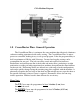
CM +Machine Diagram 1.0 CreaseMaster Plus+ General Operation The CreaseMaster Plus+ is an impact die score machine that effectively eliminates substrate cracking experienced with rotary scoring. The CreaseMaster Plus+ is microprocessor controlled, making it easy to set up and program. It has the program ability to hold a maxiumum of 20 jobs with 10 creases. Inverted and regular scoring can be accomplished in one pass. The jobs can all be stored and recalled for future use.
2.0 Machine Assembly Remove and unpack all machine parts from the shipping carton. 2.1 Power Supply Instructions Before connecting the power cord to a wall receptacle, make certain the supply voltage is what the machine has been set up for. The voltage is marked on the sticker containing the serial number of the machine. If there are any discrepancies, please call your dealer first before plugging the machine in.
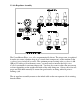
2.2 Air Regulator Assembly The CreaseMaster Plus+ score dies are pneumatically driven. The air pressure is regulated from the air source (whether shop air or a stand-alone compressor) on the machine at the regulator/gauge/manifold assembly. The optimum pressure setting at the regulator is 60100 psi. If scoring a job with many scores, you may need to increase the Impression Control to maintain a consistent impression.
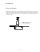
3.0 Getting Ready 3.1 Paper Gate Adjustments • With light to medium stock, the feed finger should be not adjusted down, as the front nozzles will hold the stack in position. Heavier and/or wider stock may require the feed finger to be lowered to the point that it will hold back the second sheet but allow the first sheet to pass.
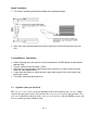
3.2 SELF CENTERING AIR FEED Side Rail Set-up • • • • • • Set single sheet between side rails and bring side rails into meet sheet edges. Check the sheet slides smoothly between side rails. Set Skew on Op Side Rail using graduated marks along slot edges and Skew Adjust Knob. Place sheet back in and confirm that it slides smoothly between full length of rails before tightening the Skew adjust Knob on the Non-Op Side Rail. Place Stock in feeder and set front air nozzles (see next section).
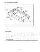
Nozzle Positioning • The nozzles should be positioned according to the following diagram • Note: Very wide stock will require the nozzles to be closer to the feed finger than the side rails.
4.0 Setting Up a Job Follow the instructions on the touch screen control board. If you experience any difficulties contact your local dealer first. If you still require assistance please call Graphic Whizard technical support at 1-800-265-3376 (available in North America only).
4.1 OPERATING THE TOUCH SCREEN This is the initial start up screen that appears once the machine is turned on. Approximately 2 minutes after the screen was last touched, the screen will go into a sleep mode to conserve power and extend the life of the screen. Touch anywhere on the screen to make it active again. To begin programming a new job, press the “Program New Job” key.
This screen appears after pressing the “ Program New Job ” key. The number “1” signifies the first crease you are going to program. Press the 0.00 key to enter the distance from the lead edge of the piece of paper to be creased to the position of the first crease. Touch the numbers that represent this distance. Use the Decimal (.) key to enter fractions of an inch/centimetre i.e. 5.5 Press the Back Space (BS) key to erase the last number entered if incorrect.
Pressing the Previous (PREV) key will return you back to the previous screen displayed. You will not lose information programmed into the crease positions unless you press the MAIN key where crease #1 and #2 are displayed on the screen. Program any remaining creases in the same way you did previously.
After the 10th crease is programmed, pressing the NEXT key will advance you to the Strike Perf screen. Pressing the CREASE COMPLETE key will also advance you to the Strike Perf screen which is the next area requiring programming. Note: Strike Perf is an option that must be ordered from your dealer. It allows a perf line to be turned on and off on a page rather than running the length of the page. If your machine does not have the Strike Perf option, proceed to page 15 after pressing the OFF key.
This screen is the first one to be displayed should you want to use the pneumatic Strike Perf option OR if you want to continuously perf a page. If you want to continuously perf using a standard accessory holder, press the OFF key to advance to the next screen. To program the Strike Perf option, press the ON key and skip to page 18 of these instructions.
CONTINUOUS PERF USING STANDARD ACCESSORY HOLDER This screen does not affect continuous perf. Press the SKIP TEST PAGE key to advance to the next screen.
CONTINUOUS PERF USING STANDARD ACCESSORY HOLDER Press the RUN key to begin the job.
CONTINUOUS PERF USING STANDARD ACCESSORY HOLDER Press the RUN key to start the job running. Pressing the MAIN Key will return you to the initial programming screen. Press the CNTCLR key to zero the counter so that the system will count each sheet being perfed. If the machine times out while the job is running due to lack of paper in the feeder, simply press the RUN key to resume. Once the job is complete, press the MAIN key to return to the initial programming screen.
If you want to use the Strike Perf accessory holder to do continuous perfing, press the ContinuousPerf OFF key so that it displays ContinuousPerf ON. If you want to program the Strike Perf option, press the NEXT key to move to the next programming screen.
Press the 0.00 key to activate the keypad menu. Enter the length of the page and press the Enter ( ) key to proceed. Press the NEXT key to move to the next programming screen.
The Strike Perf option can be programmed to come on and off up to 5 times for each piece of paper. Press the 0.00 key to program the position where you want the Strike Perf to begin. Once programmed, press the Enter ( programming screen. Press the 0.00 ) key to return to the key to program the distance from the lead edge where the Strike Perf is to turn off. Press the NEXT key to program more Strike Perf locations.
Program Strike Perf as in Strike Perforation 1 on the previous page. Press NEXT to program more Strike Perf locations. If no more Strike Perf locations are needed, press the PERFCOMPLETE key.
Program Strike Perf as in Strike Perforation 1 on page 20. Press NEXT to program more Strike Perf locations. If no more Strike Perf locations are needed, press the PERFCOMPLETE key.
Program Strike Perf as in Strike Perforation 1 on page 20. Press NEXT to program more Strike Perf locations. If no more Strike Perf locations are needed, press the PERFCOMPLETE key.
After programming the 5th Strike Perf location, pressing the NEXT key or PERFCOMPLETE key will advance you to the next screen. Please Note: If a Strike Perf is to start at the ledge edge of the sheet you must perf at least 3.5 inches before turning the strike perf off. If you do not start at the lead edge of the sheet the closest position you can start the strike perf is 3.
The Speed and Impression control keys do not effect the operation of the Strike Perf. Press RunTestPage to see the results of the programming. Press SkipTestPage if you want to move to the next screen without seeing a test page. NOTE: The pump must be turned on to feed paper properly. Only look at the first page as subsequent pages may have fed into the machine but the programming only properly runs on the first test page.
Pressing PREV takes you back one screen to where you can select to run a test page or not. The Run and Save key allows you to program a name for the job you have just programmed. (See page 27) The Run key will start the job programmed without saving it for use at a later date. (See page 32) The Go to Edit Menu will allow you to alter both the creases programmed and the Strike Perfs programmed before proceeding further.
Press the key to activate the keypad. The and keys scroll through the whole alphabet in upper and lower case and also give you access to numbers and some symbols. Once completed, press the Enter ( ) key to proceed. The screen will display the name you typed in. Touch the box with the name in it if you want to edit it. If not, press NEXT key to continue.
Once you have read this message, press NEXT to continue. The UP and DOWN keys referred to in the message are 2 screens forward from here.
Once you have read this message, press NEXT to continue.
This screen displays job numbers and the name they were saved under. Use the UP and DOWN keys to change the program number displayed so that you can save in an empty job number or override the one you want to. Press SAVE key when you are in the spot you want to be.
Pressing the Run Now key advances you to the run menu. (See page 32) Pressing the Return to Main Menu key returns you to the initial Welcome screen. The job has been saved and can be recalled by pressing the Run Existing Job key on the Welcome screen.
The Run menu screen allows you to control certain aspects of how the job will run. The speed can be adjusted using the UP and DOWN keys to move the number displayed from 1-10. 10 is the fastest, 1 the slowest. Once it is known that the stock is running well, increase the speed as high as possible for maximum productivity. Slow the system down if jamming occurs due to curled stock or other factors. The impression strength can also be adjusted UP or DOWN from 1-6.
Press the UP or DOWN keys so that the job to be run is displayed. Press the OPEN SAVED PROG key to proceed.
If the contents of the saved program are known and do not need editing, press the RUN AS DISPLAYED key to proceed. Return to page 32 for instructions on the Run Menu. If you want to review or edit the saved program, press the EDIT key and go to Page 11 for further instructions.
5.0 Idler Wheels/Perforating/Slitting 5.1 Idler Wheels The Idler Wheels (rubber tires on the accessory holders) are used to stabilize the stock as it passes over the boss wheel shaft, especially in the situation where a perf or slit are set up. They should be positioned 1-1½ in/2.6-4.4 cm from the edges of the paper with a minimum amount of contact pressure. Skewing of the stock can be adjusted slightly by increasing/decreasing pressure.
Perforating, and/or slitting can be performed with or without a score. As previously mentioned, if no scoring is desired, program ‘00’has been set aside for this task. The perforator blades are available with 2,4,6,8 and 12 teeth per inch as well as Microperf. The blades can be easily interchanged using the ring pliers supplied with the machine. Remove the accessory holder from the machine. Simply remove the retaining clip from the blade hub and pop off the blade.
through the machine square, you can feed a sheet into the machine using the hand wheel and align the lead edge of the sheet with a straight edge in the machine (such as the edge of the boss shaft). To adjust the squareness of feed, you can move the front or back of the operator side feed rail on the feed table to make sure the sheet travels through the machine squarely. If you adjust the operator side feed rail, you must adjust the nonoperator side rail as well.
6.0 Maintenance 6.1 Cleaning After each job, or halfway (approximately 24 hrs) through a very long job, it is recommended that the machine be blown off with compressed air to remove dust from the moving parts. Blanket wash may be used to remove ink from rollers/tires. Occasional application of a rubber roller rejuvenator will help keep the rollers/tires in good shape. The machine should have a thorough cleaning once a week. 6.
Page 40
Page 41
Page 42
Page 43
Page 44
PARTS PART NO. Jr. 3K 6K 8K 8KP 12K FM FM CM 100 150 PRO FRIC PLUS (J-1) CM CM AIR DESCRIPTION FEED 10-001-GW X X X X X X Red, Preinked Pad w/holder 10-002-GW X X X X X X Black, Preinked Pad w/holder 10-003-GW X X X X X X Uninked pad w/holder 10-004-GW X X X X X X Felt Insert 10-005-GW X X X X X X Red Ink, 2 oz. bottle 10-006-GW X X X X X X Black Ink, 2 oz.
10-031-CM X 10-032-GW X X X 10-032-DH X Main Top Roller X Main Platen Crash Pad OP Crash Pad GW 8000 PDS 10-033-GW X X X X X Main Platen 10-033-OSL X X X X X Main Platen Deflector X X X X X Main Platen Grommets 10-033-CM X 10-034-GW 10-035-GW X X X Deflector Platen / Die X X X X X Main Platen Mount Brackets 10-040-GW X X X X X X Hand Knob 10-041-GW X X X X X X 5/16" Disc Spring 10-042-GW X X X X X X 5/16" Flat Washer 10-043-GW X X X X
10-095-GW X X X X X X X X X X 10-102-GW X X X X X X X X X X 16 TPI Perf.
20-007-GW X Forward/Back Adjustment Screw 20-008-GW X Head Height Adjustment Screw 20-010-GW X Footpedal w/Cord 20-015-GW X 20-016-GW X X X J-1 Wire Connecotr Speed / Impression Control Harness 25-004-GW X Circuit Enclosure 25-009-GW X Switch Plate/Circuit Mount 25-012-GW X Circuit Board- external impression control 30-009-GW X X X X X X X X X X 1/2" main structure shaft 30-011-GW X X X X X X X X X X shaft adjust blocks 30-025-GW X X X X 30-037-GW X X
70-003-GW X X Feeder Side Plate 70-006-GW X X Feed Platen 70-007-GW X X Feed Pulley w/spur gear 70-008-GW X X 1 ½” Feed Pulley 70-013-GW X X Ball Bearing Holder Mount Block 70-013B-GW X X X X X X Regulator Bracket 70-014-GW X X Steel Ball Bearing 70-015-GW X X Nylon Ball Bearing 70-019-GW X X O-Ring Drive Belt (Register Board) 80-007-GW X X Controller Board (115 VAC) 80-007-GW-X X X Controller Borad(115 VAC) Exchange 85-007-GW X X Controller Board (230VAC)
90-034-GW X Display Board Label SN 2110 AND LOWER 90-034S-GW X 90-054-GW X X X X X 90-055-GW X X X X X 90-059-GW X X X X X 90-060-GW X X X X X MSTP Board 120V Connector 90-061-GW X X X X X MSTP Board 220V Connector X X X Operator Side Cover Strip 3k Print Head Mount Screws Print Head Rotation Screw X X X X X 220V Line Cord 90-062-GW X X X X X X X 110V Modular Switch w/fuseholder 90-062K-GW OP OP OP OP OP OP OP OP OP OP 220V Modular Switch w/fus
94-072-GW X X Pneumatic Drive Unit 94-073-GW X X Complete Pneumatic Drive Unit w/Reverse #ring Head 94-083-GW X X LV Solenoid to MSTP Board Power Cable 94-084-GW X X Drive Unit Connection Metal Plate 96-009-GW X X 96-012-GW X X Register Guide 96-015-GW X X Register Board Ball Holder 96-017-GW X X Register Board Cross Shaft Supports 96-018-GW X X Register Board Bearing Blocks 96-023-GW X X Register Board Conveyor Spool 96-024-GW X X Non-Operator Side Stock Guide X
CM-0005 X X X Photo Sensor Cross Bracket CM-0006 X X X Spacer Block CM-0007 X X X End Support Block CM-0008 X X X Cylinder Mount Bracket CM-0009 X X X Cross Brace Bracket Support CM-0010 X X X Metal Display Panel CM-0030 X X Main Top Roller CM-0031 X X X Main Bottom Roller CM-0034 X X X Display Panel Label CM-0034S X X CreaseMaster Pro Strip CMP-002 Pnuematic Cylinder CMP 003 X X X Solenoid Valve CMP-004 X X X Stepper Motor CMP-005 X X X Touch
FLD-0112 X X Pump Switch Plate FLD-0116 X X Magnetic Back Stop FLD-0117 X X Vacuum Belt FLD-0121 X X Paper Gate Support Shaft FLD-0124 X X Static Eliminator FLD-0126 X X Pump On/Off Switch FLD-0130 X X Vacuum Pump 110V FLD-0131 X X Vacuum Pump 220V FLD-0135 X X Hose Clamps FLD-0136 X X Snaploc Hose FLD-0137 X X Snaploc 90 Degree Elbow FLD-0138 X X Snaploc 1/4F-18NPT Connector FLD-0139 X X Snaploc 1/4NPT To 1/4 Snaploc FLD-0140 X X Hose Barb X X 7" Ru
RN031 X X X X X X pawl mount shaft RN032 X X X X X X comb spring RN033 X X X X X X 2-piece comb spring (condensed head) RN034 X X X X X X comb spring mount screw RN035 X X X X X X knocken RN036 X X X X X X knocken mount screw RN044 X X X X X X repeat selector mount screw RN050 X X X X X X split spring pin RN055 X X X X X X nylon washer RN100 X X X X X X repeat selector assembly (6-digit standard head) RN100A X X X X X X r