C60 VoIP Phone User Manual Cortelco 1703 Sawyer Road Corinth, MS 38834 USA www.cortelco.com Tel: (662)287-5281 Fax:(662)287-3889 Version 1.
Safety Notices Please read the following safety notices before installing or using this phone. They are crucial for the safe and reliable operation of the device. Please use the external power supply that is included in the package. Other power supplies may cause damage to the device, affect the behavior or induce noise. Before using the external power supply, please be sure it is for use with your power voltage. Incorrect power voltage may cause fire and damage.
Table of Contents 1 INTRODUCING C60 VOIP PHONE............................................................................... 7 1.1 THANK YOU .......................................................................................................................... 7 1.2 BOX CONTENTS .................................................................................................................... 7 1.3 KEYPAD ...........................................................................................
.3 REDIAL / UNREDIAL ........................................................................................................... 18 4.4 CLICK TO DIAL .................................................................................................................... 18 4.5 CALL BACK ......................................................................................................................... 18 4.6 AUTO ANSWER ...............................................................................
7 ADVANCED SETTINGS ................................................................................................ 26 7.1 GENERAL............................................................................................................................ 26 7.2 ACCOUNT ........................................................................................................................... 26 7.2.1 Basic Settings ......................................................................................
8.3.4.3 DIAL PLAN ...................................................................................................................... 57 8.3.4.4 CONTACT......................................................................................................................... 59 8.3.4.5 REMOTE CONTACT ....................................................................................................... 61 8.3.4.6 WEB DIAL ..............................................................................
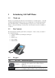
1 Introducing C60 VoIP Phone 1.1 Thank you Thank you for purchasing the C60 Voice Over Internet Protocol (VoIP) telephone. The C60 is a fully featured telephone that provides voice communication over the data network. This phone has all the features of a traditional telephone and gives access to many data service features. This guide will help you easily use the various features and services available on your phone. 1.2 Box Contents The following items should be packed with your telephone.
added. To exit Phone Book mode, press and hold this key. Mute During a call press this key to prevent the distant party from hearing the conversation. The distant party will still be heard. Line1/2 The C60 has 3 SIP lines. The user may select either of them to place a call if they have been registered to a SIP server. Volume -/+ Adjust the volume by pressing these two keys. Redial Speaker phone Indicator light Soft key 1/2/3/4 When off hook, this will dial the last called number.
1.4 Port 1.
In handset mode In headset mode SMS Missed call Call forward 1.6 LED Introduction 1.6.1 Programmable key LEDs for BLF LED Status Steady green Slow blinking red Steady red Fast blinking red Off 1.6.2 Programmable key LEDs for Presence LED Status Steady green Slow blinking red Steady red Fast blinking red Off 1.6.3 Description The object is idle. The object is ringing. The object is active. The object has failed. Not subscribed. Description The object is online. The object is ringing.
1.6.4 Programmable key LEDs for MWI LED Status Blinking Green Off 1.6.5 Power Indication LED (Power Light Enabled) LED Status Steady red Blinking red Off 1.6.6 Description There are new voice mails. There is no new voice mail. Description Power on. There is an incoming call. Power off. Power Indication LED (Power Light Disabled) LED Status Blinking red Description There is an incoming call 2 Initial Connection and Setting 2.1 Connecting the phone 1. a. b. Connect to the network.
2. Connect the handset to the handset jack using the handset cable in the package. 3. Connect the power supply to the DC port on the back of the phone. Connect the power supply to a standard power outlet. Note that the power supply will not be needed if your network provides Power over Ethernet (PoE). 4. The phone’s LCD screen displays “INITIALIZING”. Later, a ready screen displays the date, time and current network mode.
20. 21. 22. 23. 24. 25. 26. 27. 28. Use LEFT ARROW or RIGHT ARROW to enable PPPoE. Press SAVE softkey. Press BACK softkey to return to the WAN Settings screen. Press UP ARROW or DOWN ARROW to scroll to “1. Connection Mode.” Press OK. Use LEFT ARROW or RIGHT ARROW to select “PPPoE.” Press SAVE softkey. Press BACK or EXIT 6 times to return to idle screen. Disconnect and reconnect the power supply so the phone will reboot and apply the new settings. 2.2.2 1. 2. 3. 4. 5. 6. 7. 8. 9. 10. 11. 12. 13. 14. 15.
33. Press BACK or EXIT 6 times to return to idle screen. 34. Disconnect and reconnect the power supply so the phone will reboot and apply the new settings. 2.2.3 1. 2. 3. 4. 5. 6. 7. 8. 9. 10. 11. 12. 13. 14. 15. 16. 17. 18. 19. 20. 21. 22. 23. 24. 25. DHCP Mode Press the MENU softkey. Scroll down to “3. Settings.” Press OK. Scroll down to “2. Advanced Settings.” Press OK. The LCD will display “INPUT PASSWORD”. Input the password (default value is 123). Press ENTER. Scroll down to “2. Network.” Press OK.
screen. The number may also be dialed first. Then the method of speaking can be chosen. 3.1.2 Call Methods Press an available line button then use one of the following methods to place a call. 1. Dial the desired number using the keypad. 2. Press the History softkey. Use the navigation buttons to highlight the number to call. Use the LEFT ARROW or RIGHT ARROW to choose Missed Calls, Incoming Calls and Outgoing Calls. 3. Press the REDIAL button to redial the last number called. 4.
phone number for forwarding. 5. Press Save to save the changes. 3.5 Call Hold 1. Press the Hold softkey to put the active call on hold. 2. If there is only one call on hold, press the Hold softkey to retrieve the call. 3. If there is more than one call on hold, press the line button, and the Up/Down button to highlight the call, then press the Resume button to retrieve the call. 3.6 Call Waiting 1. Press Menu ->Features->Enter->Call Waiting->Enter. 2.
3.9.3 Semi-Attended Transfer During a conversation, press the XFER key, dial the number to which the call is to be transferred. Then press the Send softkey. When the third party phone begins to ring, press XFER to complete the transfer. NOTE: Call waiting and call transfer must be enabled. 3.10 1. 2. 3. 4. 5. 6. 3-way conference call Press the CONF softkey during an active call. The first call will be placed on hold and dial tone will be heard. Dial the number to be added to the conference. Press Send.
*2* is the code. After saving the above configuration, A can dial *2* plus the number for B or C to join B and C’s call. The prefix can be set to anything the user desires that does not interfere with other dialing rules. 4.3 Redial / Unredial If B is on a call when A calls, A will get busy tone. If A wants to connect to B as soon as B is available, he can use the redial function. To use this feature, A dials a prefix and then B’s number.
4.8 Application 4.8.1 SMS 1. Press Menu ->Applications->Enter->SMS->Enter. 2. Use the navigation keys to highlight the options. Messages can be read in the Inbox/Outbox. 3. Press Reply to reply to a message. Use the 2aB softkey to change the Input Method. After entering the reply, press OK, use the navigation keys to select the line from which you want to send, then press Send. 4. To write a new message, press New. Use the 2aB softkey to change the Input Method.
4.9 Programmable Key Configuration The phone has 12 programmable keys which can be set to various functions. The functions are discussed in the following sections. The default configuration for each key is None which means the key has not been set for any function. To configure any function 1. Press Menu->Settings->Basic Settings->Keyboard->DSS Key Settings. 2. Choose Line Key Settings or Function Key Settings. 3. Use the UP ARROW or DOWN ARROW to choose the key. 4.
F_LOCK – Locks the keypad. F_SMS – Send SMS F_LOR – Call Back F_POWER – Turn Power LED On or Off F_SDTMF – Send DTMF F_PREFIX – Enter prefix to be dialed. Ex: Access Code for outside line. F_HOTDESKING – Clears all SIP information and registers new SIP information. 4.9.4 DTMF Dials a programmed number. 4.9.5 URL Directly accesses a remote XML phonebook. 4.9.6 None No function. 5 Other Functions 5.
4. Use LEFT ARROW or RIGHT ARROW to Enable. 5.4 Ban Outgoing If this function is enabled, the phone cannot make outgoing calls. Press Menu ->Features-> Ban Outgoing-> Enter. 5.5 Dial Plan 1. Press Menu ->Features-> Enter->Dial Plan-> Enter. 2. The following items in the dial plan can be enabled or disabled: Press # to Send, Timeout to Send, Timeout, Fixed Length Number, Press # to Do BXFER, BXFER On Onhook, AXFER On Onhook. Note: It is recommended that Dial Plan be configured from the web interface.
5.10 Ring from Headset When this function is enabled, ring sound will be passed to a connected headset. Press Menu ->Features-> Enter-> Headset Ring -> Enter. 5.11 Power Light This feature enables the power light at the bottom of the phone. Press Menu ->Features-> Enter->Power LED-> Enter. 5.12 Hide DTMF This feature sets how DTMF digits are displayed after a call is in progress. For example, dialing a PIN code to access banking information. 1. Press Menu ->Features-> Enter->Hide DTMF-> Enter. 2.
6 Basic Setting 6.1 Keyboard 1. Press Menu ->Settings-> Enter->Basic Settings-> Enter->Keyboard->Enter. 2. There are four sets of keys which can be configured. a) DSS Keys – Keys on the right side of the phone beside the Speakerphone button or Line Keys. b) Programmable Keys – Arrow keys and OK key c) Desktop Long Pressed – Action to take when Programmable Key is pressed and held. d) Soft Key – Keys under the display 3. Use UP ARROW or DOWN ARROW and Enter to select the key. 4.
standard types and 3 user types. The user type can be configured from the web interface. The phone will ring at the selected type shortly after it is selected. 3. Press Save. 4. Use BACK or EXIT to return to idle screen. 6.4 Voice Volume 1. Press Menu ->Settings-> Enter->Basic Setting-> Enter->Voice Volume->Enter. 2. Use LEFT ARROW or RIGHT ARROW to select the desired voice volume from the 9 choices. 3. Press Save. 4. Use BACK or EXIT to return to idle screen. 6.5 Time & Date 1.
2. Use LEFT ARROW or RIGHT ARROW to choose English or Chinese. 3. Press Save. 4. Use BACK or EXIT to return to idle screen. 7 Advanced Settings 7.1 General For all the items in this section, Press Menu->Settings->Enter->Advanced settings->Enter, and then enter the password. The default password is 123. It can be changed in the web interface. 7.2 Account This allows configuration of SIP account parameters. After selecting one of the three available accounts, the following items may be configured. 7.
7.2.3 Service Code Sets the codes to be dialed to an IP PBX to enable or disable the following functions. 1. Mode – Selects whether or not all these codes are active. 2. DND 3. Always CFW – Always Call Forward 4. Busy CFW - Call Forward Busy 5. No Answer CFW - Call Forward No Answer 6. Anonymous 7.3 Network Enter Network settings as discussed in Section 2.2. 7.4 Security 1. Menu Password – Password to enter configuration menu. 2.
Telnet with CLI command 8.1.2 Password Configuration There are two levels of access: root level and general level. A user with root level access can browse and set all configuration parameters, while a user with general level can set all configuration parameters except server parameters for SIP or IAX2. Default user with general level: Username: guest Password: guest Default user with root level: Username: admin Password: admin The default password for the phone screen menu is 123. 8.
8.3 Configuration via WEB 8.3.1 BASIC 8.3.1.
Field Name Network Accounts 8.3.1.2 Explanation Shows the configuration information for WAN and LAN port, including connection mode of WAN port (Static, DHCP, PPPoE), MAC address, IP address of WAN port and LAN port, DHCP server status for LAN port (ENABLED or DISABLED). Shows the phone numbers and registration status for the 3 SIP LINES and 1 IAX2 server. Wizard Select the appropriate network mode.
8.3.1.2.1 Static IP If Static IP is selected, this screen will be displayed. Information provided by the ISP should be entered. Click Back to return to the Wizard screen. Click Next to go to Quick SIP Settings 8.3.1.2.2 DHCP After selecting DHCP and clicking NEXT, the Quick SIP Settings screen will appear. Click Back to return to the Wizard screen. Click Next to go to the Summary screen. 8.3.1.2.3 PPPoE If PPPoE is selected, this screen will appear. Enter the information provided by the ISP.
8.3.1.2.4 Quick SIP Settings Field Name Explanation Display Name The name shown in caller ID. Server Address SIP server address either IP address or URI. Server Port SIP server port (usually 5060). Authentication User Login name or Authentication ID. Authentication Password SIP password. SIP User Phone number. Enable Registration Submits registration information. Normally checked. Click Back to return to the IP Address screen. Click Next to see summary screen.
8.3.1.3 Call Log Outgoing call logs can be seen on this page. Field Name Start Time Duration Dialed Calls 8.3.1.4 Explanation Start time of the outgoing call Duration of the outgoing call. Account, protocol, and line of the outgoing call. Language Field name Language Greeting Words Explanation Set the language of phone. English is default. The greeting displayed on LCD when phone is idle. It has a maximum of 12 characters. Default is VOIP PHONE.
8.3.2 Network 8.3.2.1 WAN Config Field Name Active IP Address Current Subnet Mask Current IP Gateway MAC Address MAC Timestamp Explanation The current IP address of the phone. The current Subnet Mask. The current Gateway IP address. The MAC address of the phone. Time the MAC address was obtained. WAN Settings The phone supports three network modes. These are also discussed in Section 2.2. Static: Network parameters must be entered manually and will not change. All parameters are provided by the ISP.
8.3.2.1.1 Static IP If Static IP is chosen, the screen below will appear. Enter values provided by the ISP. 8.3.2.1.2 DHCP If DHCP is chosen, all configuration information will be provided by a DHCP server. Contact the ISP to determine if DHCP is used. 8.3.2.1.3 PPPoE If PPPoE is chosen, the screen below will appear. Enter the information provided by the ISP.
8.3.2.2 LAN Config Field Name IP Address Subnet Mask DHCP Service Explanation LAN static IP. LAN Subnet Mask. Activate DHCP server for LAN port. The phone must be rebooted for the DHCP server setting to take effect. NAT Enable NAT operation Port Mirror Port Mirror can only be activated in bridge mode. If activated, the data stream from the WAN port is copied to the LAN port of the phone. Enable Bridge Mode If Bridge Mode is activated, the phone will not provide an IP address for the LAN port.
Chart 1 shows a network switch with no VLAN. Any broadcast frames will be transmitted to all other ports. For example, and frames broadcast from Port 1 will be sent to Ports 2, 3, and 4. Chart 2 shows an example with two VLANs indicated by red and blue. In this example, frames broadcast from Port 1 will only go to Port 2 since Ports 3 and 4 are in a different VLAN. VLANs can be used to divide a network by restricting the transmission of broadcast frames.
Field Name Explanation Enable LLDP Packet Interval Enable or Disable Link Layer Discovery Protocol (LLDP) The time interval for sending LLDP Packets Enable Learning Function Enables the telephone to synchronize its VLAN data with the Network Switch. The telephone will automatically synchronize DSCP, 802.1p, and VLAN ID values even if these values differ from those provided by the LLDP server.
8.3.2.4 Service Port Set the port values for Telnet/HTTP/RTP on this page. Field Name Web Server Type HTTP Port HTTPS Port Telnet Port RTP Port Range Start RTP Port Quantity Explanation Specify Web Server Type – HTTP or HTTPS Port for web browser access. Default value is 80. To enhance security, change this from the default. Setting this port to 0 will disable HTTP access. Example: The IP address is 192.168.1.70 and the port value is 8090, the accessing address is http://192.168.1.70:8090.
8.3.2.5 DHCP SERVICE Field Name DHCP Client Table Leased Table Name Start IP Address End IP Address Explanation IP-MAC mapping table. If the LAN port of the phone connects to a device, this table will show its IP and MAC address. Name of the lease table. Beginning IP address of the lease table. Ending IP address of the lease table. A device connected to the LAN port will get an IP address between Start IP and End IP. Subnet Mask of the lease table. Network Gateway of the lease table.
8.3.2.6 TIME&DATE Set the time zone and SNTP (Simple Network Time Protocol) server on this page. Daylight savings time configuration and manual time and date entry are also done on this page Field Name Enable SNTP Enable DHCP Time Primary Server Secondary Server Time Zone Resync Period 12 -Hour Clock Date Format Date Separator Explanation Simple Network Time Protocol (SNTP) Settings Enable or Disable SNTP If this is enabled, phone will synchronize time with DHCP server.
Daylight Saving Time Settings Enable Enable daylight saving time. Offset(minutes) DST offset. Default is 60 minutes. Month Start and end month for DST Week Start and end week for DST Day Start and end day for DST Hour Start and end hour for DST Minute Start and end minute for DST Manual Time Settings Enter the values for the current year, month, day, hour and minute. All values are required. Note: Be sure to disable SNTP service before entering manual time and date. 8.3.3 VOIP 8.3.3.
Field Name Explanation Choose the sip line to configured (SIP 1 – SIP 3). Click the dropdown arrow to select the line. Status Shows registration status. Will show “Registered” if registered or “Unapplied” if not registered. Server Address SIP server IP address or URI. Server Port SIP server port. Default is 5060. Authentication User SIP account name (Login ID). Authentication Password SIP registration password. SIP User Phone number assigned by VoIP service provider.
Display Name Enable Registration Domain Realm Proxy Server Address Proxy Server Port Proxy User Proxy Password Backup Server Address Backup Server Port Server Name Set the display name. This name is shown on Caller ID. Check to submit registration information. SIP Domain if different than the SIP Registrar Server. SIP proxy server IP address or URI(This is normally the same as the SIP Registrar Server) SIP Proxy server port. Normally 5060. SIP Proxy server account. SIP Proxy server password.
Subscribe For MWI MWI Number Subscribe Period Conference Type Conference Number Registration Expires Enable Service Code DND On Code DND Off Code Always CFwd On Code Always CFwd Off Code Busy CFwd On Code Busy CFwd Off Code No Ans. CFwd On Code No Ans.
Local port Ring type Enable Rport Enable PRACK Enable Long Contact Convert URI Dial Without Registered Ban Anonymous Call Enable DNS SRV Enable Missed Call Log BLF List Number Enable BLF List Server Type RFC Protocol Edition Transport Protocol Anonymous Call Edition Keep Authentication Ans. With a Single Codec Auto TCP Enable Strict Proxy Enable GRUU Enable Displayname Quote Enable user=phone Click to Talk Strict Branch Enable Group Different VoIP Service providers may require different modes. SIP port.
Registration Failure Retry Time 8.3.3.2 Registration failure retry time – If registration fails, the phone will attempt to register again after registration failure retry time. This will affect all lines IAX2 Field Name Status Server Address Server Port Account Password Phone Number Local Port Voice Mail Number Voice Mail Text Echo Test Number Explanation Shows registration status. Will show “Registered” if registered or “Unapplied” if not registered. IAX2 server address. IAX2 server port.
Echo Test Text Refresh Time Enable Registration Enable G.729AB 8.3.3.3 non- numeric, this number can be used to replace the echo test text. This allows dialing a number to perform an echo voice test. This function is provided to test whether communication through the server. Echo test text Expiration time of IAX2 server registration. Allowed values are between 60 and 3600 seconds. Enable/Disable IAX2 registration. Enable/Disable G.729 codec. STUN Config STUN support is configured in this page.
Field Name STUN NAT Transversal Server Address Server Port Binding Period SIP Waiting Time SIP Line Using STUN Use STUN 8.3.3.4 Explanation Shows whether or not STUN NAT Transversal was successful. STUN Server IP address STUN Server Port – Default is 3478. STUN blinding period – STUN packets are sent at this interval to keep the NAT mapping active. Waiting time for SIP. This will vary depending on the network.
Example 2: Substitution – To dial a long distance call to Beijing requires dialing area code 010 before the local phone number. Using this feature 1 can be substituted for 010. For example, to call 62213123 would only require dialing 162213123 instead of 01062213123. Example 3: Addition – Two examples are shown. In the first case, it is assumed that 0 must be dialed before any 11 digit number beginning with 13.
Field Name Phone number Destination Port Alias Explanation There are two types of matching: Full Matching or Prefix Matching. In Full matching, the entire phone number is entered and then mapped per the Dial Peer rules. In prefix matching, only part of the number is entered followed by T. The mapping with then take place whenever these digits are dialed. Prefix mode supports a maximum of 30 digits. Set Destination address. This is optional.
The phone will add the alias to the end of the dialed number if the dialed number matches the template in the Phone Number box. Set Phone Number, Alias and Delete Length. Phone number is XXXT and Alias is rep: xxx If the dialed phone number starts with the digits in the Phone Number box, the matching digits will be replaced by the alias number. If the dialed phone number starts with the digits in the Phone Number box, the phone will send out the dialed phone number and add the suffix number. 8.3.
Third Codec Fourth Codec Fifth Codec Sixth codec Onhook Time Default Ring Type Handset Input Volume Handset Output Volume Speakerphone Volume Ring Volume G729 Payload Length Tone Standard G722 Timestamps G723.1 Bit Rate Enable VAD DTMF Payload Type The third codec choice: G.711A/u, G.722, G.723, G.729, G.726, None The forth codec choice: G.711A/u, G.722, G.723, G.729, G.726, None The fifth codec choice G.711A/u, G.722, G.723, G.729, G.726, None The sixth codec choice G.711A/u, G.722, G.723, G.729, G.
8.3.4.2 FEATURE This page configures various features such as Hotline, Call Transfer, Call Waiting, etc. Field Name Do Not Disturb Enable Call Transfer Semi-Attended Transfer Enable Auto Handdown Auto Handdown Time Enable Auto Redial Auto Redial Interval Explanation If enabled, the phone will reject incoming calls. The callers receive busy tone. Outgoing calls may be made. If enabled, Call Transfer is allowed. If enabled, Semi-Attended Transfer is allowed.
Auto Redial Times Auto Headset Enable Intercom Enable Intercom Tone P2P IP Prefix Turn Off Power Light Emergency Call Number Enable Password Dial Password Dial Prefix Password Dial Length Ban Outgoing Enable Call Waiting Enable 3-way Conference Accept Any Call Enable Call Completion Enable Pre-Dial Enable Silent Mode Hide DTMF Maximum number of auto redial attempts. Automatically answers call on headset. If enabled, allows intercom calls.
Ring from Headset Enable Intercom Mute Enable Intercom Barge DND Return Code Busy Return Code Reject Return Code Active URI Limit IP Push XML Server Enable Call Waiting Tone Action URL Settings Block Out Settings If this is enabled and a headset is connected, ring tone will be played in the headset. If enabled, mutes incoming calls during an intercom call If enabled, the phone will auto-answer an intercom call during an outside call.
8.3.4.3 DIAL PLAN This phone supports 7 dialing modes: 1. End with “#”– Dial the desired number, and press # to send it to the server. 2. Fixed Length – The number will be sent to the server after the specified number of digits are dialed. 3. Time Out – Number will be sent to the server after the specified time. 4. User Defined – Customized rules created by the user. There is a special feature in the dial plan for the case where the user must dial an access code to get an external line.
5. Press # to Do Blind Transfer - Press # after entering the target number for the transfer. The phone will transfer the current call to the third party. 6. Blind Transfer on Onhook - Hang up after entering the target number for the transfer. The phone will transfer the current call to the third party. 7. Attended Transfer on Onhook - Hang up after the third party answers. The phone will transfer the current call to the third party. [] * .
8.3.4.4 CONTACT Enter the name, phone number and ring type for each contact here.
Office Number, Mobile Number, Other Number Ring Type Group Name Office Number, Mobile Number, Other Number Line Ring Type Group Setting Contact phone numbers Ring type for this contact Contact group for this contact Add Contact Contact name Contact phone numbers Select line for associated contact number Ring type for this contact Choose the group or groups for this contact and move them to the Selected list on the right.
8.3.4.5 REMOTE CONTACT Allows access to remote contact lists either via XML or LDAP. TFTP example: Set the Phonebook Name as cortelco - Server URL is tftp://192.168.1.3/admin/phonebook/index.xml. LDAP example: Server URL is ldap://192.168.1.3/dc=winline,dc=com. Remote Phonebook Setting Phonebook Name Phonebook name displayed on the phone. Server URL Server url of the remote phonebook. SIP Line SIP line for the remote phonebook. Authentication Authentication mode for remote phonebook.
8.3.5 Function Key The phone has 8 programmable DSS/Function keys with associated LEDs and 2 programmable Line keys with LEDs. The 4 directional arrow keys and the OK button are also programmable. This screen also sets the LCD contrast and enables the backlight. For additional DSS/Function buttons, up to 5 C10 Expansion modules may be connected. 8.3.5.
Field Name Contrast Enable Backlight Screen Configuration Explanation Set screen contrast Enable/disable LCD backlight. Pickup Number Line Key Settings/Function Key Settings Explanation Key Name Select the type of function the key is to perform. Choices are: None BLF List Key – If the SIP server supports this function, the key can monitor the status of a group of phones. DTMF – Send DTMF during a call Key Event – Many different functions. See Section 4.9.3 for a list.
8.3.5.2 Softkeys Configure the functions performed by the softkeys under the LCD in various phone operating modes.
8.3.5.3 EXT Keys These are the keys on the C10 Expansion Module. Up to 5 modules may be connected to one phone. The phone can power one module. Additional modules will require a separate power supply. See the C10 documentation for installation instructions. The keys have the same capabilities as the Function Keys. 8.3.6 Maintenance 8.3.6.1 Auto Provision The phone supports PnP, DHCP, and Phone Flash to obtain configuration parameters. They will be queried in the following order when the phone boots.
Auto Provision Setting Field Name Explanation Current Config Version Show the current config file’s version. If the version of configuration downloaded is higher than this, the configuration will be upgraded. If the endpoints confirm the configuration by the Digest method, the configuration will not be upgraded unless it differs from the current configuration. Show the common config file’s version. If the configuration downloaded and this configuration are the same, the auto provision will stop.
PnP Port PnP Transport PnP Interval Server Address Protocol Type Config File Name Update Interval Update Mode PnP Server Port PnP Transfer protocol – UDP or TCP Interval time for querying PnP server. Default is 1 hour. Phone Flash Settings Set FTP/TFTP/HTTP server IP address for auto update. The address can be an IP address or Domain name with subdirectory. Specify the Protocol type FTP, TFTP or HTTP. Specify configuration file name. The phone will use its MAC ID as the config file name if this is blank.
Level 0 1 2 3 4 5 6 7 Name Emergency Alert Critical Error Warning Notice Informational Debug Description System is unusable. This is the highest debug info level. Action must be taken immediately. Critical conditions. System is probably working incorrectly. Error conditions. System may not work correctly. Warning conditions. System may work correctly but needs attention. Normal but significant condition. Normal daily messages. Debug messages normally used by system designer.
8.3.6.3 Config Setting Config Setting Field Name Save Configuration Backup Configuration Clear Configuration Explanation Save the current phone configuration. Clicking this saves all configuration changes and makes them effective immediately. Save the phone configuration to a txt or xml file. Please note to Right click on the choice and then choose “Save Link As.” Logged in as Admin, this will restore factory default and remove all configuration information.
8.3.6.4 Update This page allows uploading configuration files to the phone. Update Field Name Web Update Explanation Web Update Browse to the config file, and press Update to load it to the phone. Various types of files can be loaded here including firmware, ring tones, local phonebook and config files in either text or xml format. TFTP/FTP Update Server Address FTP/TFTP server address for download/upload. The address can be IP address or Domain name with subdirectory.
Type Protocol Action to be executed by the phone. 1. Application update - download system update file 2. Config file export - Upload config file to FTP/TFTP server. It can then be named and saved. 3. Config file import - Download the config file from FTP/TFTP server. The configuration will be effective after the phone is reset. 4. Phone book export (.vcf, .csv, .xml) - Upload the phonebook file to FTP/TFTP server. It can then be named and saved. 5. PhoneBook import (.vcf, .csv, .
8.3.6.5 Access User accounts can be added or deleted from this page. The authority of accounts can also be changed. Access Configuration Field Name Explanation LCD Menu Password Settings Menu Password Sets the password for entering the setup menu from the phone keypad. The password must be only digits. User Settings This table shows the current user accounts Add User User Set User Account name User Level There are two levels. Root user can modify the configuration.
8.3.6.6 Reboot Some configuration modifications require a reboot to become effective. button will cause the phone to reboot immediately. Note: Be sure to save the configuration before rebooting. 8.3.7 Security 8.3.7.1 WEB FILTER Clicking the Reboot WEB Filter The Web filter is used to limit access to the phone. When the web filter is enabled, only the IP addresses between the start IP and end IP can access the phone.
8.3.7.2 Firewall Firewall Configuration Firewall rules can be used to prevent unauthorized Internet users from accessing private networks connected to this phone (input rule), or prevent unauthorized devices connected to this phone from accessing the Internet (output rule). Each rule type supports a maximum of 10 items.
When a connected device tries to access 192.168.1.118, the phone will deny the request because of the out_access rule. Access to any other IP address will be allowed. Click the Delete button to delete the selected rule. 8.3.7.3 Network Address Translation (NAT) NAT is the process of modifying IP address and port information in transition from a private to a public network. NAT allows the use of one public address to support many private addresses.
connectivity to specific hosts in the internal network, although communication with other hosts in the DMZ and to the external network is allowed. This allows hosts in the DMZ to provide services to both the internal and external network, while a firewall controls the traffic between the DMZ servers and the internal network clients. The following chart describes the network access control of DMZ.
Network Address Translation (NAT) Table Shows the NAT TCP and UDP mapping tables NAT Table Option Transfer Type Select the TCP or UDP protocol. Inside IP Set the local IP address of device. Inside Port Set the LAN (inside) port for NAT mapping Outside Port Set the WAN (outside) port for NAT mapping Note: After entering settings, click the Add button to add new mapping table data. To delete an entry, enter its information and then click the Delete button. Notice: The phone supports 10M/100M adaptive.
VPN Server Address VPN User VPN Password 8.3.7.5 Security Field Name Select Security File Select Security File SIP TLS File HTTPS File OpenVPN Files 8.3.8 Set VPN L2TP Server IP address. Set User Name access to VPN L2TP Server. Set Password access to VPN L2TP Server. Explanation Update Security File Browse to the security file to be updated. Click the Update button to update. Delete Security File Select the security file to be deleted. Click the Delete button to Delete.
9 Appendix 9.1 Specification 9.1.1 Hardware Item Power Adapter Specification Operation Temperature Relative Humidity CPU SDRAM Input: 100-240V Output: 5V 1A 10/100Base- T RJ-45 1 PORT 10/100Base- T RJ-45 1 PORT RJ45 1 PORT RJ9 1 PORT Idle: 2.5W Active: 2.8W 128x64 53.5 x 70mm 0~40℃ 10~65% Broadcom 16MB Flash 4MB Dimension(L x W x H) Weight 295×295×175mm 1.5kg Port WAN LAN EXT Headset Power Consumption LCD Size 9.1.2 Voice Features Supports 3 SIP servers Supports RFC3261 Codecs G.
SIP domain SIP authentication none basic MD5 DNS Peer to Peer/ IP call Automatic line selection 9 Standard ring tones and 3 user-defined ring tones DTMF SIP info DTMF Relay (In-Band) RFC2833 AUTO SIP applications Call Forward Call Transfer(Blind/Attended) Hold Call Waiting 3 Way Conference SMS Remote Pickup Join Call Redial Unredial Multi-line Intercom BLF Presence Push to talk Auto Redial Call Back Call control features Flexible dial pl
Phonebook 500 records Incoming Calls Outgoing Calls Missed Calls Max of 300 Records Each Supports vCard/XML/CSV Support IAX2 2 Programmable Line/DSS keys 8 DSS keys Programmable Soft Keys Programmable Function Keys Code synchronization IP PBX IMS Supports Click to Dial via Web Phone Book Supports DSS Consoles (5 Max) Keypad Lock with Emergency Call Customized LCD logo as screensaver Ring Tone via Headset or Speaker Customized Signal Tone Parameters Time Display 12
9.1.
9.2 Digit-character map table Keypad Character Keypad 1@ Character 7PQRSpqrs 2ABC ab c 8TUVtuv 3DEFdef 9WXYZwxyz 4GHIghi */.