
Manual


COSA Instruments USER MANUAL COSA 707
www.cosaxentaur.com
12
6 ANALYZER DESCRIPTION
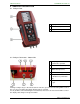
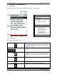
6.1 Analyzer front
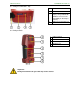
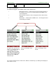
6.2 Analyzer Connectors - bottom side
Note:
If during zeroing T air (5) is disconnected, then value of T gas at the end of zeroing will be used. In
this case, the measuring value will be displayed green coloured.
If T air (5) will be connected during the measurement, then true T air measurement will occur and
the display color changes from green to black.
1 Display
2 Condensate separator
3 Key pad
1 Sampling probe connection
Condensate separator
2 Pressure connection 1 (Draft)
3 Pressure connection 2
(Differential pressure)
4 Connector AUX (optional)
5 Temperature connection 1 /
T-Ambient air (combustion
air)
6 Temperature connection 2 /
T-gas