INSTALLATION, OPERATION AND MAINTENANCE MANUAL COSA 9610™ GENERAL PURPOSE & EXPLOSION PROOF Version: 1.4.1 Software version: 3.10.0.0 Revision date: Mar 30, 2011 Print date: 03/30/11 CAL.01.D.
INSTALLATION, OPERATION AND MAINTENANCE MANUAL – COSA 9610™ COSA INSTRUMENT CORPORATION New Jersey Sales Office: 55 Oak Street Norwood, NJ 07648 Tel: 201-767-6600 Fax: 201-767-6804 Texas Sales & Service Offices: 7125 North Loop East Houston, TX 77028 Tel: 713-947-9591 Fax: 713-947-7549 New York Corporate & Manufacturing Offices: 84G Horseblock Rd. Yaphank, NY 11980 Tel: 631-345-3434 Fax: 631-345-5349 E-mail: sales@cosaxentaur.com http://www.cosaxentaur.com Copyright © 2009 All rights reserved.
INSTALLATION, OPERATION AND MAINTENANCE MANUAL – COSA 9610™ Table of Contents 1. INTRODUCTION ................................................................. 5 1.1. INTRODUCTION .............................................................................. 5 1.1.1. Purpose of the analyzer ...........................................................................5 1.2.1. 1.2.2. Oven with oxygen sensor.........................................................................6 The sample system (SCS) .
INSTALLATION, OPERATION AND MAINTENANCE MANUAL – COSA 9610™ 3.2.2. 3.2.3. Programming the measurement parameters............................................21 Main screen ..........................................................................................21 3.3.1. 3.3.2. 3.3.3. 3.3.4. 3.3.5. 3.3.6. 3.3.7. 3.3.8. Calibration Menu ...................................................................................26 Operation Menu ......................................................................
INSTALLATION, OPERATION AND MAINTENANCE MANUAL – COSA 9610™ 1. INTRODUCTION 1.1. 1.1.1. INTRODUCTION Purpose of the analyzer The continuous COSA 9610™ analyzer determines online the Wobbe-index of a gas. The COSA 9610™ can be used both, as feed forward and feedback analyzer for gases mixing or as a feed forward analyzer for burning control. In order to achieve an optimal performance of the analyzer system it is necessary to read this manual thoroughly before installation and start-up.
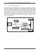
INSTALLATION, OPERATION AND MAINTENANCE MANUAL – COSA 9610™ 1.2.1. Oven with oxygen sensor The gas/air mixture is burnt catalytically in an oven, which is kept at 812ºC with a burning spiral. The temperature is maintained with a temperature controller using a K-type thermocouple. The oxygen sensor in the oven is a zirconium oxide cell. This is mounted such, that one side is in contact with the outside air and the other side with the flue gasses.
INSTALLATION, OPERATION AND MAINTENANCE MANUAL – COSA 9610™ 1.2.2. The sample system (SCS) In the sample conditioning system (SCS), gas and air are mixed in a constant proportion, such that a small excess of air is present (± 2.5% oxygen) in the flue gas. The gas and air pressure, are equalized by a dome-loaded pressure reducer (or booster relay), where the gas pressure governs the air pressure.
INSTALLATION, OPERATION AND MAINTENANCE MANUAL – COSA 9610™ 1.3. CALIBRATION PROCEDURE The analyzer can be calibrated in three different ways: • • • Single point calibration Only one calibration gas is used. The value of the gas is chosen middle of the measuring range. This is only used to correct any offset error to the measurements. Two point calibration Two calibration gases are used. The low calibration gas is set at ± 20% of the measuring range.
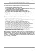
INSTALLATION, OPERATION AND MAINTENANCE MANUAL – COSA 9610™ The two-point calibration/validation procedure will be executed as followed: 1. Analyzer activates calibration/validation contact. 2. The procedure pauses for the specified “Calibration Start Delay” time for the external host to prepare for calibration/validation. 3. Process gas is switched off and the low calibration gas is switch on. 4. The analyzer waits for the readings to stabilize up to the “Switch Time”. 5.
INSTALLATION, OPERATION AND MAINTENANCE MANUAL – COSA 9610™ 1.4. 1.4.1. EXTENDED (DUAL) RANGE OPTION Operation When the measuring range of the analyzer is larger than 1150BTU/SCF, an extended range option is available which covers a Wobbe index of 3000.BTU/SCF. This is accomplished by adding a second gas-mixing orifice and selection valves to make changeover possible. The dilution ratios of each mixing orifice are chosen such that the measuring ranges overlap.
INSTALLATION, OPERATION AND MAINTENANCE MANUAL – COSA 9610™ 1.5. 1.5.1. SPECIFICATIONS COSA 9610™ WOBBE INDEX ANALYZER Analyzer performance Make Service Ranges Accuracy Repeatability Drift Response time Output Cosa Instrument Corporation Natural gas, fuel-gas, biogas, etc. Wobbe index 0-3000 BTU/scf (0-95 MJ/Nm3), span 0-1150 BTU/scf (40 MJ/Nm3) (selectable CARI 0-20, span 0-10) ± 0.4% of measuring value natural gas ±0.7 BTU/scf (±0.03 MJ/Nm3) ±0.4 BTU/scf (±0.
INSTALLATION, OPERATION AND MAINTENANCE MANUAL – COSA 9610™ 2. INSTALLATION 2.1. GENERAL Upon receipt and unpacking of the COSA 9610™ a visual inspection must be carried out to check for any visual damage, caused by transport.
INSTALLATION, OPERATION AND MAINTENANCE MANUAL – COSA 9610™ 2.3.2. COSA 9610™ in general purpose execution (Type 01 & 02) The COSA 9610™ is to be mounted against an even wall or structural steel construction. Fixing lugs are located on each corner of the cabinet. Fixings used must be suitable for the weight of the COSA 9610™ (±331 lbs/150kg).
INSTALLATION, OPERATION AND MAINTENANCE MANUAL – COSA 9610™ 2.4. 2.4.1. • • • • • • • • • • • • • • • • • MECHANICAL CONNECTIONS General Location and amount of connections may vary depending on type and execution of the analyzer. See the project specific drawings of your order. Tubing connections on the COSA 9610™ are Swagelok double ferrule compression type fittings for imperial sizes.
INSTALLATION, OPERATION AND MAINTENANCE MANUAL – COSA 9610™ • • If the body is not damaged the pipe has to be cut just after the nut and newly installed according above instructions using new ferrules. (The nut can be re-used) Disconnected fittings can be re-installed by hand tightening the nut followed by wrench tightening for 1/4 turn. It is recommended to perform a leak test after reinstallation. 2.4.2.
INSTALLATION, OPERATION AND MAINTENANCE MANUAL – COSA 9610™ The COSA 9610ª requires one power supply. ∞ Analyzer electronics (ATEX application). The power has to be connected on the interference filter inside the electronics cabinet. The cable has to lead into the analyzer through a suitably certified cable gland. ∞ Analyzer electronics (NEC US application). The power has to be connected on the interference filter inside the electronics cabinet.
INSTALLATION, OPERATION AND MAINTENANCE MANUAL – COSA 9610™ Signal cables The COSA 9610™ has multiple input and output signals, which can be split in two groups, analog and digital signals. Both analog and digital signals are to be connected in the electronics enclosure. Please make sure that the cable glands used are suitably certified. For details see project specific drawings. Control equipment connected to barrier must not use or generate more than 250Vrms or 250Vdc.
INSTALLATION, OPERATION AND MAINTENANCE MANUAL – COSA 9610™ 3. IN OPERATION 3.1. START-UP SAMPLE CONDITIONING SYSTEM The sample conditioning system is located in the left-hand compartment. This chapter describes how the components of the sample conditioning system should be set up, in correct order, so a perfect start-up of the total analyzer system can be achieved. The instructions hereunder should be performed step by step. 3.1.1.
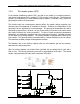
INSTALLATION, OPERATION AND MAINTENANCE MANUAL – COSA 9610™ Relationship of pressure differential (gas/air) versus Wobbe-Index with different air orifices and a fixed residual oxygen concentration of 5% (theoretically determined). It is therefore recommended that a residual oxygen concentration of 2.5% is chosen corresponding to the reference point.
INSTALLATION, OPERATION AND MAINTENANCE MANUAL – COSA 9610™ !Caution The adjusting screw is located in the gas compartment of the relay. When the insert is released, gas will escape. Be prepared before the relay is going to be adjusted, e.g. have the right equipment readily available, so the gas compartment has to be open for only a minimum of time. After this adjustment the insert must be fitted again and the offset can be checked.
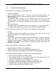
INSTALLATION, OPERATION AND MAINTENANCE MANUAL – COSA 9610™ 3.2. START-UP OF THE CONTROL UNIT This chapter describes the procedure to start up the control unit. When a machine is being started up for the first time a gas calibration has to be done first. 3.2.1. Description 3.2.2. Programming the measurement parameters Programming the COSA 9610™ is easy with the menu-controlled software. Menu can be navigated using the cursor keys.
INSTALLATION, OPERATION AND MAINTENANCE MANUAL – COSA 9610™ Page 22 of 44
INSTALLATION, OPERATION AND MAINTENANCE MANUAL – COSA 9610™ The lower right section displays the status of each digital input and output. The signal assignments are user-programmable.
INSTALLATION, OPERATION AND MAINTENANCE MANUAL – COSA 9610™ Global Settings 1. Calibration Menu Tree V2.3.0.0 1. Start Calibration 2. Start Validation 3. Calibration gases 4. Settings 1. Gas 1 Wobbe 1. automatic 5. Schedule 2. Operation 3. Measurement 1. General 2. Multi-Stream 3. Dual Range Semi- 1. Sunday 2. Monday 3. Tuesday 2. Remote 3. Timed 4. Timed Method 4. 5. 6. 7. 5. 6. 7. 8. Wednesday Thursday Friday Saturday Start Delay Switch Time Error Detection Error Limit 2. Gas 1 CARI 3.
INSTALLATION, OPERATION AND MAINTENANCE MANUAL – COSA 9610™ 4. Output (Analog & During Cal) 1. 2. 3. 4. Channel Channel Channel Channel A B C D 5. Communication 1. Modbus 2. Serial 3. Ethernet 6. System 1. About 2. Date & Time 3. Login 7. Display 4. Password 1. Chart 1 2. Chart 2 3. Color 8. Reset Alarms (User 1234) Password 5. Logout (Admin Password 9999) 6. Configuration 7. Test 8. Restart 9 Exit 1. Analog Output A 2. Analog Output B 3. Analog Output C 4. Analog Output D 5.
INSTALLATION, OPERATION AND MAINTENANCE MANUAL – COSA 9610™ 3.3. PROGRAMMING MENUS The paragraph numbers correspond with the key sequence from the ‘menu tree’. In this way it is easy to see how a specific menu is reached. One exception is the measuring menu, this is reached from the main screen by either the ! or Enter key. 3.3.1.
INSTALLATION, OPERATION AND MAINTENANCE MANUAL – COSA 9610™ 3.3.2.
INSTALLATION, OPERATION AND MAINTENANCE MANUAL – COSA 9610™ 3.3.3.
INSTALLATION, OPERATION AND MAINTENANCE MANUAL – COSA 9610™ 3.3.4.
INSTALLATION, OPERATION AND MAINTENANCE MANUAL – COSA 9610™ 3.3.5.
INSTALLATION, OPERATION AND MAINTENANCE MANUAL – COSA 9610™ Page 31 of 44
INSTALLATION, OPERATION AND MAINTENANCE MANUAL – COSA 9610™ 3.3.6.
INSTALLATION, OPERATION AND MAINTENANCE MANUAL – COSA 9610™ Display Menu Page 33 of 44
INSTALLATION, OPERATION AND MAINTENANCE MANUAL – COSA 9610™ 3.3.7.
INSTALLATION, OPERATION AND MAINTENANCE MANUAL – COSA 9610™ 3.4. 3.4.1. TEMPERATURE CONTROLLED OVEN Furnace temperature control unit The zirconia cell must operate at a temperature above 600ºC. For optimal performance, a set-point temperature of 812ºC was chosen. The oven that serves as the heating device for the zirconia cell is made of a metal wire-wound heating element. To minimize energy consumption, the heating element is encapsulated by glass-fibre insulating material.
INSTALLATION, OPERATION AND MAINTENANCE MANUAL – COSA 9610™ NOTE: Set oven temp to 81 2ºC & sample system to 50ºC for standard units, 90ºC for mid-temp models 3.4.2. Adjustment procedure temperature regulator This procedure describes the setting of the temperature controller. The controller measures the temperature with the help of a K-type thermocouple. The heating is arranged by a pulsing 5VDC signal. The on/off relation decides the added capacity.
INSTALLATION, OPERATION AND MAINTENANCE MANUAL – COSA 9610™ 4. PREVENTIVE MAINTENANCE 4.1. 4.1.1. WEEKLY / MONTHLY MAINTENANCE Compressor (optional) Checking for moisture. If the indicator on the drier has changed colour from light blue to lilac or pink, this indicates that the drier is saturated and is not working efficiently. If the indicator is discoloured, the supplier of the compressor should be contacted. 4.1.2. 4.2. 4.2.1.
INSTALLATION, OPERATION AND MAINTENANCE MANUAL – COSA 9610™ 4.3. • • • • • • ANNUAL MAINTENANCE Check the calibration gas bottles for pressure. Check the sample system for correct pressure. Check the bypass flow meter for correct flow rate. Replace the instrument air filters as required. Replace optional sample gas filters as required. Replace optional pump diaphragms as required.
INSTALLATION, OPERATION AND MAINTENANCE MANUAL – COSA 9610™ 4.4. TROUBLESHOOTING Breakdown -> fault report Test Action No air pressure -> flow alarm tube fracture Replace tube Measuring pressure reducing valve behind Open valve for reducing valve tagged “air supply” Increase output pressure No gas pressure -> flow alarm Tube fracture Close main valve immediately and replace pipe Blockage in gas supply Check/clean/replace tubing Check set point on temp. Controller.
INSTALLATION, OPERATION AND MAINTENANCE MANUAL – COSA 9610™ 4.5. REPLACEMENT OF RESIDUAL OXYGEN SENSOR Before going any further make sure that the oven has been disconnected and cooled off so that no physical injury can occur caused by coming into contact with any parts which may still be hot. 1. Remove the connecting clips from the sensor and take care that the ceramic ring stays in place. 2. Unscrew the sensor from the cell holder. 3.
INSTALLATION, OPERATION AND MAINTENANCE MANUAL – COSA 9610™ 5. INSTALLATION DRAWING Standard drawing shown with optional equipment.
INSTALLATION, OPERATION AND MAINTENANCE MANUAL – COSA 9610™ 6. ORDERING OF SPARE PARTS All spare parts may be ordered quoting number and specification from: Installation and maintenance by trained personel only: COSA INSTRUMENT CORPORATION New Jersey Office: 55 Oak Street Norwood, NJ 07648 Tel: 201-767-6600 Fax: 201-767-6804 Texas Office: 7125 North Loop East Houston, TX 77028 Tel: 713-947-9591 Fax: 713-947-7549 New York Office: 84G Horseblock Rd.
INSTALLATION, OPERATION AND MAINTENANCE MANUAL Ð COSA 9610ª CAL.S1.E.0200 CAL.S1.E.0520 CAL.S1.M.0001 CAL.S1.M.0002 CAL.98.M.0088 CAL.S1.M.0005 CAL.S1.M.0006 CAL.S1.M.0007 CAL.S1.M.0022 CAL.S1.M.0023 CAL.S1.M.0025 CAL.S1.M.0026 CAL.S1.M.0033 CAL.S1.M.1000 CAL.S1.M.2000 CAL.S2.M.0001 ESS.37.M.0575 CAL.98.M.0007 XDO.98.M.5022 XDO.98.M.5023 CHA.98.M.0008 CAL.98.M.0003 CAL.98.E.0012 CAL.18.E.0000 CAL.60.E.0001 CAL.60.E.0002 CAL.98.M.0117 CAL.98.M.0116 CAL.98.M.0115 CAL.98.E.0068 CAL.S1.E.0005 CAL.98.M.0009 CAL.
7. CERTIFICATION 1. ATEX CERTIFICATE 2. US/CANADIAN CERTIFICATE This product has been examined against the following standards 1. ATEX: EN 60079-0:2009 EN 60079-2:2007 EN 60079-11:2007 EN 60529 (+A1):2000 84F HORSEBLOCK RD. YAPHANK, NY 11980 U.S.A. TEL: 001-631-345-3434 1725 TYPE/MODEL HAZARDOUS AREA PROTECTION DEGREE CATEGORY CERTIFICATE : WIM 9610: Ex ib px llC T3 Gb Ta=+5C to 45C, lP66. : ll 2G : FM11ATEX0006X SERIAL No.