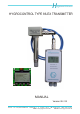
H ygrocontrol GmbH HYGROCONTROL TYPE 86-EX TRANSMITTER MANUAL Version 06 / 05 Feuchte- und Temperatur-Meßtechnik Fax.: 06181-927930 Moselstraße 2 B, D-63452 Hanau, Tel.: 06181-92790 Internet: www.hygrocontrol.de e-mail: info@hygrocontrol.
HYGROCONTROL Manual for Type 86 Ex Page 1 Table of Contents 1. General Informations 1.1 1.2 Intention of this Manual Before Using / Safe Operation under EX-Conditions 3 3 1.2.1 1.2.2 1.2.3 Unpacking and Checking Setup for Operation On-Site Preparations to fullfill Ex-Regulations 3 3 4 1.3 Instructions for Dispatch 4 2. Technical Data 5 2.1 2.2 2.3 2.4 2.5 2.
HYGROCONTROL Manual for Type 86 Ex Page 2 4. Practical Instructions and Limits 22 4.1 4.2 4.2.1 4.2.2 4.3 4.4 4.5 4.6 4.7 Contact with Liquids Filters Protection against high Air Velocities Protection against Dust and Aerosols Withstanding chemical Attack Protection of Transmitter Electronics Influence of Temperature on Humidity Measurements Humidity Measurements over Ice Measurements under Pressure and Vacuum 22 22 22 22 23 23 23 23 24 5. Operating the Instrument with Display-Option 26 5.1 5.
HYGROCONTROL Manual for Type 86 Ex Page 3 1. General Informations 1.1 Intention of this Manual This manual describes the proper use of type 86-EX instruments, their maintenance and limits. We want to beware any user from errative measurements and give examples for the usage. Please be aware that these high precision electronic instruments for humidity and temperature must have very sensitive sensors and electronics which need some care.
HYGROCONTROL Manual for Type 86 Ex Page 4 on the type label you find on one side of the housing. Do not use voltages other than the marked one! Severe damage would be the result of applying the wrong voltage. If your instrument is equipped with screw terminals, the cross section of your conductors should meet the dimensions of 0.5 up to 1.5 mm2 (AWG 16 to AWG 20).
HYGROCONTROL Manual for Type 86 Ex Page 5 2. Technical Data 2.1 Humidity Detection Ranges are possible from 0-100 %RH as well as absolute Humidities, Dewpoints and Enthalpie, programed is a range of Resolution Sensing Element (capacity type) Influence of Temperature on the Humidity Repeatability Hysteresis for 4 hours Cycle 10 % - 95 % - 10 % RH Unlinearity of Electronics / Humidity 2.
HYGROCONTROL Manual for Type 86 Ex 2.
HYGROCONTROL Manual for Type 86 Ex Explanation of EX-Labels TUV PRODUCT SERVICE H J/SN: 2004/10002 EX-Class of Instrument Ex-Zone + Temp.-class Number of Certificate Year of Production/Serialnumber Environmental Temperatures of Electronics and Probe Tube Prooving Authority TUV Transmitter Typ 86 2004/10001 EX5 04 06 52446 001 U m 230 VAC ATEX II (2) GD L i 10 µH C i 1 µF [EEx ia] II C L o 100 µH C o 5 µF PRODUCT SERVICE Class of intrinsic Safety Max.
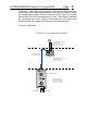
HYGROCONTROL Manual for Type 86 Ex 2.7 Electrical Connections 2.7.1 Screw Terminals 8 3 Terminals for ACor DC-Power Supply X1/1 = L, X1/2 = PE, X1/3 = N X1/1 = -, X1/2 = PE, X1/3 = + 3 Terminals for Output Humidity X2/1 = + Humidity (mA), X2/2 = GND, X2/3 = + Humidity (V) X2/4 = + Temp. (mA), X2/5 = GND, X2/6 = + Temp. (V) 3 Terminals for Output Temperature 2.7.2 Page Connector Options 7pol. round Plug according to DIN 43651 for Power (max. 42 V) and Outputs or: 1 rectangular Connector 4 pol.
HYGROCONTROL Manual for Type 86 Ex Page 9 Transmitter: Transmitters built according to EN 50020 as intrinsically safe supply instruments. Intrinsically safeness is given by Zener Barriers which are encapsulated together with the connector for the cable to the probe and therefore may not be manipulated by a user. These Barriers separate the intrinsically safe power supply for the probes from the internal and external current and voltage loops which are not intrinsically safe.
HYGROCONTROL Manual for Type 86 Ex Page 10 3. Operation Series 86-EX Humidity and Temperature Meters detect relative Humidity and Temperature. For this purpose the interchangeable probes are equipped with a capacity type humidity sensor of very small mass. The temperature detection is done by a RTD of type Pt-1000, which is placed very close to the humidity sensor to avoid differences in temperature between the two sensors.
HYGROCONTROL Manual for Type 86 Ex 3.1 Page 11 Operational Mode „MEASURING" As mentioned „MEASURING" mode is realized by : - Code Switch „S1" in position „0" - Jumper „X4" in position „M" - Power is supplied to the transmitter Now the instrument will detect values of temperature and relative humidity and send them to the outputs. To inform the user of instruments without display about this actual operation mode the LED’s „H2“ and „H4“ are lightened alternating. 3.1.
HYGROCONTROL Manual for Type 86 Ex Page 12 The current outputs may be set to be 0-20 mA or 4-20 mA. Normally your desired version is programed by the factory - if you want to change it please see chapter „CONFIGURATION” where you find how to do this. 3.1.2 Tables of analogue outputs Following tables show some examples of relations between outputs and ranges for temperature and relative humidity. 3.1.2.1 Examples for outputs of relativ humidities (0 - 100 %) % r. F.
HYGROCONTROL Manual for Type 86 Ex 3.1.2.2 °C -50 -40 -30 -20 -10 0 10 18 19 20 21 22 30 40 50 60 70 80 90 100 110 120 130 140 150 Page 13 Examples for outputs of different Temperature Ranges (Analogue Output of 0 - 20 mA) -50..+150 -30...+70 -25...+75 -20...+80 -20...
HYGROCONTROL Manual for Type 86 Ex 3.1.2.3 Page 14 Examples for different Outputs of Temperature Ranges (Analogue Output 4 - 20 mA) °C -50..+150 -50 -40 -30 -20 -10 0 10 18 19 20 21 22 30 40 50 60 70 80 90 100 110 120 130 140 150 4,00 4,80 5,60 6,40 7,20 8,00 8,80 9,44 9,52 9,60 9,68 9,76 10,40 11,20 12,00 12,80 13,60 14,40 15,20 16,00 16,80 17,60 18,40 19,20 20,00 -30..+70 -25..+75 -20..+80 -20..
HYGROCONTROL Manual for Type 86 Ex Page 15 3.1.3 Display As an option a digital display is available. The display is arranged under the cover of the transmitters housing. It will be connected by one of the two 20-pol. female sockets in the PC-Board in the direction the user wants and is to be seen through the window in the cover. Humidity values are shown in the upper line of the display, values of temperature in the lower line.
HYGROCONTROL Manual for Type 86 Ex Page 16 The solutions we supply for calibration create rel. humidities from 0 to 95%. We are using the following: 0% - drying granulate 10% - mixed LiCl and ZnCl2 solution 20, 35, 50, 65, 80, 95% - unsaturated LiCl solutions The marked rel. humidities relate to a temperature of 22°C and do have a temperature dependency. The accuracy of the solutions at 22°C is +/0.5%, they are not toxic and are not dangerous to the environment.
HYGROCONTROL Manual for Type 86 Ex 3.2.3 Page 17 When makes a Calibration Sens? If you decide to do a recalibration, you first should detect the deviation which arised from the last recalibration. Our probes are calibrated at 7 points at least, to get a very close fit to the real sensor characteristic. If you see a deviation of more than 5%RH when trying to recalibrate a point, you should stop the calibration and delete the calibration memory totally.
HYGROCONTROL Manual for Type 86 Ex 3.2.5 Page 18 Calibration Procedure Proceed as follows: - Mount the calibration chamber as described before - Remove the bottom of the chamber to fill it with the desired solution - Break the neck of the ...
HYGROCONTROL Manual for Type 86 Ex Page 19 If no further calibrations are wanted, replace the calibration chamber now by the filter of the probe. 3.2.5 Escape the running Calibration If you want to interrupt the calibration procedure after the LED „H3” is already in a steady state, turn the code switch „S1” in any other position and put the code bridge „X4” to „M” position. Now you may turn the code switch „S1” back to „0”.
HYGROCONTROL Manual for Type 86 Ex Page 20 Table 2 Code Switch „S1” Position 0 1 2 3 4 5 6 7 8 9 A B C D-E F Activated Function Signal Output Measuring Mode Adjustment of Humidity Output at lower Limit Adjustment of Humidity Output at upper Limit Adjustment of Temperature Output at lower Limit Adjustment of Temperature Output at upper Limit Adjustment of Humidity Range at lower Limit Adjustment of Humidity Range at upper Limit Adjustment of Temperature Range at lower Limit Adjustment of Temperature Ra
HYGROCONTROL Manual for Type 86 Ex Page 21 20 mA - and the ranges should be set to -50°CTd to +50°CTd and –20 to +80°C, then the upper limit 50°CTd is set by an output of 8 mA and the upper limit +80°C is set by an output of 10,4 mA (= 0,08x80 + 4,0)).
HYGROCONTROL Manual for Type 86 Ex 4. Page 22 Practical Instructions and Limits Besides the temperature limits specified for all our transmitters, probe heads and sensors, you should observe the following rules when using our instruments: 4.1 Contact with Liquids Avoid in any case direct contact between the humidity sensor and any liquid. The sensor may only detect the humidity in the atmosphere over the surface of a liquid or a solid material.
HYGROCONTROL Manual for Type 86 Ex 4.3 Page 23 Withstanding Chemical Attack Our sensors are wellknown for their resistance against most chemical attacks. To give the user some informations over the additional errors which are arising from some chemicals, we listed our experiences over the last 10 years. (See the table at the end of this manual). Be aware, that the given concentrations are valid for a single chemical in normal atmosphere (room temperature) only.
HYGROCONTROL Manual for Type 86 Ex Page 24 Table 3: Display at 100% RH over Ice at different Temperatures Temperatur (°C) PSF (mbar) PSE (mbar) M (%RH) 0 6,11 6,11 - 5 4,22 4,02 95,3 - 10 2,87 2,60 90,6 - 15 1,91 1,66 86,9 - 20 1,26 1,03 81,7 - 25 0,81 0,64 79,0 - 30 0,49 0,37 75,5 100 PSF = Saturated Vapor Pressure over Chilled Water PSE = Saturated Vapor Pressure over Ice M = Rel. Humidity displayed by HYGROMESS Instruments. 4.
HYGROCONTROL Manual for Type 86 Ex Page 25 Table 4: Gas Concentrations with Humidity Error < 2.5 %RH MAK-Concentration 1) Chemical maximum Concentration according to SUVA at continuous load ppm Expl.
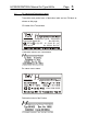
HYGROCONTROL 5. Manual for Type 86 Ex Page 26 Operating the Instrument with Display-Option From normal display of Humidity and Temperature you get into the menus for Configuration and Calibration by pressing one of the 4 buttons on the displayboard. The display now shows the different submenus you may choose: -- SETTINGS -List Calibration Data List Configurat. Data Calibrate (PW) Cofigure (PW) Display Setup = letters are white on back background and this is the submenu choosen.
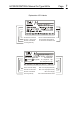
HYGROCONTROL Manual for Type 86 Ex Page 5.2 Configuration Data: Config-Data = Symbol for Humidity Out Low = 800 = 800 Digits = 4 mA With the “arrow”-buttons you come to other Config-Data. These are: Config-Data Out High = 4000 Config-Data Out Low = 800 = Symbol for Humidity = 4000 Digits = 20 mA = Symbol for Temperature = 800 Digits = 4 mA Config-Data Out High = 4000 = Symbol for Temperature = 4000 Digits = 20 mA Now the scales for Hunidity and Temperature are shown Config-Data Range Low = 0.
HYGROCONTROL Manual for Type 86 Ex Page Config-Data Range High = 100.0%RF = Symbol for Humidity = Scale ends at 100%RF Config-Data Range Low = 0.0°C = Symbol for Temperature = Scale starts at 0°C Config-Data Range High = 100.
HYGROCONTROL Config-Data Manual for Type 86 Ex Page 29 At least you will see the Ser.-No. of the Transmitter Serial number: = 00000 5.3 Calibration -- Calibrate -Password 0000 If there was choosen Calibrate (PW) in the main menu and was acknowledged by button , the Password must now be typed in. You get the first 2 digits of the 4-digit Password by the sum of the first 3 digits of the Serial number of the Transmitter. (Leading 0 must be encluded).
HYGROCONTROL -- Calibrate -ambient Temperature = 22.6 °C Manual for Type 86 Ex Page 30 The blinking digit may be changed by button . Button goes to the next digit. If the value of the ambient Temperature is typed in correct, it will be stored by pressing button . You may not change the indicated temperature value by more than 5°C! 5.