When calling for technical support..... ........ please have your serial numbers ready. The Sensor and Instrument Serial Numbers are on the rear of the instrument, also see section 5.2.4. Sensor Serial No.: _______________ Instrument Serial No.: _______________ Your Representative is: COSA INSTRUMENT CORPORATION 55 Oak Street, Norwood, NJ 07648 Tel.: (201) 767-6600 - Fax.
The customer agrees that in accepting and using this instrument Xentuar Corporation’s liability arising from or in any way connected with this instrument shall be limited exclusively to performing a new calibration or replacement or repair of the instrument or sensor, at Xentaur’s sole option.
XPDM Manual Table of Contents 1. Introduction ................................................................................................................... 1 2. Precautions ................................................................................................................... 2 3. Principle of Operation ................................................................................................... 3 4. Operating the XPDM..................................................................
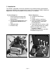
1. Introduction The XPDM is a portable, hand-held, microprocessor controlled, battery operated dewpoint meter with built in dry-storage for the sensor. The instrument is ideally suited for all applications, where quick and precise measurements are required. Standard Equipment: 1. XPDM Portable Instrument with sensor, desiccant cartridge and lithium battery. 2. 2VCO® to Swagelok® fittings and 2 Swagelok® to barbed hose fittings. 3. Calibration bulb. 4. Shoulder strap. 8 Optional Equipment: 5.
2. Precautions • • • • • • • • • Warranty limitation: The XPDM’s sample cell/piston assembly should not be disassembled except by factory trained personnel. The warranty is voided, if the sample cell piston assembly is disassembled by the customer. Avoid contaminated sample streams: The XPDM has been designed to allow for fast and precise measurements of dewpoints as low as -100 °C. Therefore, all surfaces in contact with the sample stream are made from electropolished stainless steel.
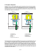
3. Principle of Operation Dewpoint sensors, like all hygroscopic materials, adsorb much faster than they desorb. Therefore, an accurate measurement will be obtained much faster, if at the beginning of the measurement, the sensor is at a dewpoint drier than the gas to be measured. The XPDM design allows the sensor to be moved directly between dry-storage and the sample cell, without any exposure to ambient air.
A note about dry-storage The dry-storage consist of a stainless steel container filled with desiccant. The electropolished stainless steel sensor guard slides between the dry-storage and the sample cell through a spring energized PTFE seal, assuring maximum possible gas tightness and minimum gas transport between the two chambers when the sensor is moved. When in dry-storage, the sensor guard is separated from the desiccant by a stainless steel wire mesh with a thickness of 127µ (0.
4. Operating the XPDM 4.1. Sample Hook-up 4.1.1. Fittings The XPDM can be hooked up to the sample gas using a variety of fittings, depending on the application. The instruments’ sample ports are 1/4” VCO® female, to assure proper seals for even the lowest dewpoint measurements.
• sufficient, assist by gently pulling on the sensor actuator located on the front of the instrument, while still blocking the sample outlet port. Observe the change in dewpoint indication. The reading will be stable within about 3 minutes, if the dewpoint is increasing. A longer stabilization period will be required, if the dewpoint is decreasing. Make sure the reading has completely stabilized before taking the final reading.
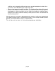
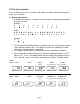
5.0 The User Interface The user interface consists of a custom LCD display, an audio indicator, 5 push buttons and a sensor actuator. 5.1 Display Conventions 1. To display letters with the 7 segment numeric display, the following pseudo-alphanumerics are used: Numbers: 0 1 2 3 4 5 6 7 8 9 Letters: A B C D E F G H I Symbols: ? - ! " J L N O P Q R S T U X Y Z . # 2.
5.2 Operating State Refer to Appendix A for a flow diagram of the operating state. The XPDM is powered ON by pressing the ‘Power’ button until a beep is heard; to activate the backlight, continue to depress the ‘Power’ button until the backlight turns on. Keep in mind that with the backlight on the unit consumes about 5 times more power. Upon power up the unit performs certain initialization tests (see section 9), and enters the ‘Operating State’, in the Viewing Dewpoint mode.
back to atmospheric settings. A long press of the pressure correct button changes the unit back to the Viewing Dewpoint Mode. Pressing the ‘Mode’ button changes the unit to the View/Set Gas Pressure sub-state. The display has the ‘SET’ and ‘PSI’ legends on and alternately shows and the currently set value for the gas pressure. The up, down and pressure correct buttons operate in the same manner as in the Sensor Pressure sub-state.
1999 then it is displayed in 2 parts, first part is the thousands signified by the x103 legend in the upper right corner of the display and the second part is the units. For example serial number 12345 will be shown as: 3 x10 Pressing the ‘Mode’ button changes the unit to the Viewing Dewpoint Mode. 5.3 Set-up State To enter the Setup State power-up the unit while depressing the Mode key. Refer to Appendix B for a flow diagram of the Set-up State.
6. Options The instrument can be optionally equipped with an output/power supply board, to allow for the following capabilities: 1. RS-232C. 2. Current Loop output (4-20mA or 0-24mA). 3. Operation from an external power supply e.g. a wall transformer. 6.1 RS-232C The RS-232C output is provided on a 9 pin sub “D” female connector, located at the rear of the instrument. The configuration is 9600 baud, Even Parity, 7 Bits, 1 Stop.
If the current loop is not being used, it is safe to connect the DB9 connector directly to a PC; pins 1&9 will not be damaged or cause damage. The RS-232 levels are generated by the instrument only when an RS-232 level is detected at the DB9 input. Therefore, when operating from a battery to conserve its power, disconnect the RS-232 cable unless necessary for the operation. 6.
6.3 Operating from an external Power Supply The external power connector is a 2mm power jack located on the rear of the unit. This input can accept either AC or DC power and is thus polarity independent. The unit requires 13VDC to 25VDC, when operating from external DC power. The unit requires 12VACrms to 25VACrms, when operating from external AC power. In either case the unit can draw up to 50mA when the backlight is on and supplying current loop output. The power input is protected with a 250mA fuse.
7. Automatic Calibration The instrument is calibrated at the factory with the shipped sensor, and does not need to be re-calibrated prior to use. Do not re-calibrate the unit unless you suspect a problem. The XPDM instrument takes advantage of the pre-designed saturation point of Xentaur HTF™ sensors.
8. Changing desiccant cartridge and/or battery. In order to change desiccant cartridge and/or battery, remove the two thumb screws on the rear cover. These screws are approximately seven inches long and after they are loose must be pulled out. If the instrument has a filter bracket installed the screws holding the bracket to the bottom cover must also be removed. Then the bottom cover may be removed.
9. Special messages, warnings and error indications LO TEMP HI TEMP Unidentified power-up failure. Legend: if problem persists, return to your representative A/D converter failure. for service. Reference voltage for A/D out of spec. Low battery voltage. Instrument low temperature range has been exceeded. Instrument high temperature range has been exceeded. Sensor circuit is open.
Appendix A: Flow diagram of User Interface in the Operating State For backlight, hold until it comes on Flashing PSI means pressure corrected dewpoint Toggle Pressure Correct Display ˚F 1/2 sec Viewing Dewpoint PSI { ¡DEWPOINT 30 seconds anywhere (other than "Autocal") without key press Power ON initialization and sign on message SHORT PRESS units LONG PRESS AND PSI MODE Toggle 14.
Appendix B: Flow Diagram of User Interface in the Set-Up State For backlight, hold until it comes on & Power ON initialization and sign on message Test Analog Output by forcing it to high and low end or midpoint. Hi/Lo (E. G. if DB9 connector pin 9 is grounded, Hi =20mA, Lo=4mA, Mid=12mA) Hi Lo Mid Choose alternate units to show when displaying dewpoint. SET blank ˚F ˚C ppm LBS G/m3 PSI % ˚C˚F Temp˚F Temp˚C { Factory default is blank, (there is no alternate display).
Appendix C: Relationship of Instrument Reading and 4-20mA output when lbs of H20/million standard cft or ppmv engineering units are selected. Instrument reading in ppmV 0 2000 4000 6000 8000 10000 12000 14000 16000 18000 20000 22000 20 19 18 XTR100 17 16 15 4/20 mA output 14 13 12 11 10 9 8 7 6 5 4 0 100 200 300 400 500 600 700 800 900 1000 1100 Instrument reading in LBS of H2O / million standard cubic feet Instrument reading in ppmV 4.5mA 289.1 LBS = 0˚C = 6063.
Appendix D: Uncertainty in LBS and PPMV calculations Uncertainty of LBS-H2O calculation due to +/-3˚C measurment accuracy -20 -25 -30 -35 Measured Dewpoint ˚C -40 -45 -50 -55 -60 3˚C nt - oi wp -65 De -70 ˚C t +3 oin p ew D -75 30 20 7 8 9 10 6 4 5 3 2 0.7 0.8 0.9 1 0.6 0.4 0.5 0.3 0.2 0.07 0.08 0.09 0.1 0.06 0.04 0.05 0.02 0.
Appendix E: Battery Life Relative Battery Life Comparison Number of 10 minute samples performed 0 100 200 300 400 500 600 700 800 900 1000 1100 1200 1300 9.5 Battery Voltage 9.0 8.5 Lithium battery supplied w/unit 8.0 Alk Unit operates properly, but "BAT / LO" message appears once every 2 minutes, as a warning. Battery Voltage insufficient for proper operation, "BAT / LO" message appears continuously. alin e av He ty Du y- 7.5 nc Zi 7.