
Specifications


3
3. INSTALLATION, CONNECTION
Two or more Slim Stick S LED modules can be installed by joining them with special couplers. A heat sink
mounted LED module has superior reliability.
●
●●
●Installation Procedure
(1) Installation with screws
Use M3 bolts (round head diameter < 0.7mm) for mounting LED module.
The LED module is equipped with one guide hole. Use this hole for positioning the LED module.
There are five mounting holes in addition to the guide hole. At least two holes must be secured with bolts.
[NOTE] In the case of 30 LED types (STW0101N, STN0101N), pay attention that the holes' line is
offset from the LEDs' line.
(2) Installation with double-faced tape
The LED modules can be installed with double-faced tape. (Recommended tape: NITTO 5000N)
Guide hole
30 LEDs (STW0101N, STN0101N)
15 LEDs (STW0201N, STN0201N)
Guide hole
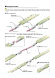
BJB coupler Screw
If the screw is secured without the above
spacer, the LED module will warp 2mm
stressing the part.
●
●●
●When plates are used:
Plates (Thickness: 2mm)
Washers (Thickness: 2mm)
Offset : 0.7mm
Pay attention not to warp the Slim Stick S-Type while installing. A warped installation will
have shorter LED module life and low reliability.
When the special BJB connector is used for coupling LD modules, a 2mm gap will exist due
to the coupler's thickness. To remedy this, a plate, washer or spacer of 2mm thickness mus
t
be used to mount the LED module with bolt.
W
ARNING
PWB
2mm
●
●●
●When washers are used:
2mm
2mm
* When a metal plate is used, the insulator mus
t
be placed between the back of the circuit board
and the metal plate. Apply the appropriate
insulator such as vinyl tape to the metal plate.