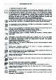
IMPORTANT SAFETY INSTRUCTIONS Carefully read the following Important information redarding installation safety and maintenance. Keep these instruction for future reference.
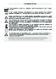
1.INSTRUCTIONS FOR USE ……………………………………………………………2-3 2.INSTRUCTIONS FOR DISPOSAL OUR ENVIRONMENTAL CARE…………… …4 3.INSTALLING THE APPLIANCE………………………………………………………5 3.1 Electrical connection………………………………………………………………6 3.2 Room ventilation ………………… ………………………………………………6 3.3 Extraction of the products of combustion … ………………………………………6 3.4 Connection to gas …………………………………………………………………7 4. ADAPTATION TO DIFFERENT TYPES OF GAS ……………………………………8 4.1 Replacement of nozzles on the cooking hob ……………………………………8 4.
TO REPLACE IT.
1)Appliance type:Class 2 2)Warning the user against the use of cooking vessels on the hotplate that overlap its edges. 3)This appliance shall be installed in accordance with the regulations in force and only used in a well ventilated space.Read the instructions before installing or using this appliance.
4
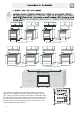
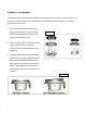
inches 6” 30” 30 inches 6” 30” 6” 30” 30.1” 35.4” 30” 6” 30.1” 35.4” 23.6” 23.6” 23.6” 23.6” 3.93” - 5.3” 23.6” 23.6” 23.6” 30” 23.6” B) Free-standing installation A) Built-in appliance 6” 3.93” - 5.3” 6” 30” 6” 30” 6” 30” 30.1” 30.1 “ 35.4” 35.4” 23.6” 23.6” 23.6” 23.6” 3.93” - 5.3” 3.93” - 5.3” 35.4” 35.4” A) Built-in appliance 35.
E Warning: 1)Prior to installation, ensure that the local distribution conditions(nature of the gas and gas) pressure)and the adjustment of the appliance are compatible; 2)The adjustment conditions for this appliance are stated on data plate; 3)This appliance is not connected to a combustion products evacuation device.It shall be installed and connected in accordance with current installation regulations.Particular attention shall be given to the relevant requirements regarding ventilation.
steel steel length is no moving parts or is Gas It’s necessity of changing the flexible tube when the national conditions require it. steel steel steel steel steel hose steel steel steel 122 F). 3.4.2 1.
8
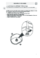
ASSEMBLY OF THE BURNERS The electrode of the electronic ignition system is positioned above the surface of the burner base. Do not remove a burner cap or touch the electrode of a burner while another is turned on. Damage or electrical shock may occur. 1. Place burner heads over the burner base. Make sure the hole in the burner head is Figure 13 properly aligned with the electrode in the burner base. (See Figure 13) 2. Place the burner caps on the burner heads.
Liquefied Petroleum (Propane) Gas Conversion Failure to make the appropriate conversion can result in serious personal injury and property damage. The conversion must be performed by a qualified service technician in accordance with the kit instructions and all local codes and requirements. Failure to follow instructions could result in serious injury or property damage. The qualified agency performing this work assumes responsibility for the conversion.
1) Unscrew the regulator cap with the wrench. (See Figure 15) 4) Reverse the retainer pin and put back into the regulator cap. This is how the regulator pin looks for LP gas usage. (See Figure 18) Figure 15 2) This is how the retainer pin looks for Natural Gas usage. (See Figure 16) Figure 18 5) Screw the regulator cap back into the regulator and re-attach the regulator to the nipple and flare union. (See Figures 12 and 19) Figure 16 3) Remove the retainer pin.
B. CHANGE BURNER NOZZLES INSTALLATION TIP: First remove all nozzles and then start replacing them. This will help to prevent the possibility that some may not be replaced. 1) Remove the burner grates, burner caps and burner heads. 2) Using a 7mm nut driver, remove the burner nozzles.
C. ADJUST BURNER FLAMES 4) To adjust the flame, remove the knobs; 1) Turn all burners on highest setting and insert a screwdriver through the access check the flames. They should be blue hole in valve shaft as shown. Make the in color and may have some yellow adjustment by slowly turning the screw tipping at the ends of the flame when until flame appearance is correct. (See using LP gas.
TESTING FLAME STABILITY Test 1——Turn the knob from “HI” to “LO” quickly. If the upper row of flames goes out at this setting, increase the flame size and test again. Test 2——With the burner on “LO”, open and close the cabinet door under the range. If the flame is extinguished by the air currents created by the door movement, increase the flame height and test again. D. FLAME RE-CHECK After the adjustment is made, turn all burners off. Ignite each burner individually. Observe the flame at the “HI” position.
(24 in. models) 1.Rapid 2 2 2 2 3.Auxiliary 1 3 4 4.Triple ring 3 4.5 (36 in. models) 2 1 2 5 1.Rapid 4 3.Fish 4.Auxiliary 2 5 4.6 4.6.1 15 2 3 4 5.
4.6.
℉ MIN 270 ℉ MIN 300 355 MAX 410 460 ℉ MIN 270 ℉ MIN 300 355 MAX 410 ℉ 17 460
120 10 20 30 120 40 50 110 60 100 90 80 70 MAX.
Caution:Glass lids may shatter when heated.
7.3 φ min Saucepan (mm) φ min Saucepan (mm) Auxiliary 3.54” 6.30” Semi-rapid 5.12” 7.09” 12.2” × 5.51” 15” × 9.06” Rapid 6” 10.24” Triple ring 8.27” 10.
527 F , 8.2 8.2.1 ℉ MIN 300 355 MAX 410 455 8.2.2 The use of a gas cooking appliance results in the production of heat and moisture in the room in which it is installed.Ensure that the kitchen is well ventilated: keep natural ventilation holes open or install a mechanical ventilation device(mechanical extractor hood).
8.3 ℉ MIN 300 355 MAX 410 455 8.
23
24
25
Oven door style 1: Remove and assemble procedure · Open door fully · Lift up and turn the small levers situated on the two hinges fully back · Grip the door on the two external sides; shut it slowly until door contacts the clips. Then continue closing door until it is about 10cm from closing fully. · Pull the door towards you, pulling it out of its seat. Door will gently come away from oven. · To reassemble the door follow the above procedures backwards.
27
K I TC H E N P RO D U CTS