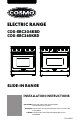
ELECTRIC RANGE COS-ERC304KBD COS-ERC365KBD SLIDE-IN RANGE INSTALLATION INSTRUCTIONS IMPORTANT: READ AND SAVE THESE INSTRUCTIONS. FOR RESIDENTIAL USE ONLY. INSTALLER: PLEASE LEAVE THESE INSTRUCTIONS WITH THIS UNIT FOR THE OWNER. OWNER: PLEASE RETAIN THESE INSTRUCTIONS FOR FUTURE REFERENCE. Rev.24.
THANK YOU FOR YOUR PURCHASE Thank you for your purchase. We know that you have many brands and products to choose from and we are honored to know that you have decided to take one of our products into your home and hope that you enjoy it. COSMO Appliances are designed according to the strictest safety and performance standard for the North American market. We follow the most advanced manufacturing philosophy. Each appliance leaves the factory after thorough quality inspection and testing.
TABLE OF CONTENTS RANGE SAFETY.................................................................................................... 4 Anti-tip Device ........................................................................................................... 5 INSTALLATION REQUIREMENTS ........................................................................ 7 Tools and Parts .......................................................................................................... 7 Location Requirements .....
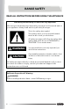
RANGE SAFETY READ ALL INSTRUCTIONS BEFORE USING THE APPLIANCE Your safety and the safety of others are very important. We have provided many important safety messages in this manual and on your appliance. Always read and obey all safety messages. This is the safety alert symbol. This symbol alerts you to potential hazards that can kill or hurt you and others. All safety messages will follow the safety alert symbol and either the word "WARNING" or "CAUTION.
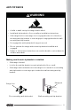
ANTI-TIP DEVICE WARNING TIP OVER HAZARD • A child or adult can tip the range and be killed. • Install anti-tip bracket to floor or wall per installation instructions. • Slide range back so rear range foot is engaged in the slot of the floormounting anti-tip bracket or rear range pin is engaged under the wallmounting anti-tip bracket. • Re-engage the anti-tip bracket if range is moved. • Do not operate the range without anti-tip bracket installed and engaged.
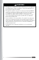
WARNING • This appliance is intended for normal residential use. It is not approved for commercial use, outdoor installation, or any other application not specifically allowed by this manual. • This appliance requires connection to a 3-prong or 4-prong, 240VAC single-phase (split-phase), 60Hz grounded electrical source dedicated to the appliance.
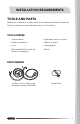
INSTALLATION REQUIREMENTS TOOLS AND PARTS Gather the required tools and parts before starting installation. Read and follow the instructions provided with any tools listed here.
PARTS SUPPLIED Control knobs 30" Model: COS-ERC304KBD (4) 36" Model: COS-ERC365KBD (6) Oven door handle Handle end caps with set screws (2) Rear rubber pads (2) Floor-mounting anti-tip bracket with mounting screws 30" Model: COS-ERC304KBD Wall-mounting anti-tip bracket with mounting screws 36" Model: COS-ERC365KBD NOTE: • To purchase these replacement parts or any other accessories, please visit www.cosmoappliances.com or reference the contact information at the end of this manual.
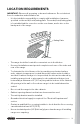
LOCATION REQUIREMENTS IMPORTANT: Observe all governing codes and ordinances. Do not obstruct flow of combustion and ventilation air. • It is the installer's responsibility to comply with installation clearances specified on the model/serial/rating plate. The model/serial/rating plate is located behind the oven door on the oven frame, and is also on the back panel of the range. Rating Plate • The range should be located for convenient use in the kitchen.
IMPORTANT: To avoid damage to your cabinets, check with your builder or cabinet supplier to make sure that the materials used will not discolor, delaminate, or sustain other damage. Mobile Home - Additional Installation Requirements • The installation of this range must conform to the Manufactured Home Construction and Safety Standard, Title 24 CFR, Part 3280 (formerly the Federal Standard for Mobile Home Construction and Safety, Title 24, HUD Part 280).
PRODUCT SPECIFICATIONS Model COS-ERC304KBD Description 30" Electric Range Oven Capacity 4.8 cu. ft. Electrical Requirements 120/240VAC 60Hz, 120/208VAC 60Hz Power Ratings Refer to Rating Plate Exterior Dimensions (WxDxH) 29 ⁷⁄₈" x 29 ³⁄₄" x 36 ¹⁄₈" (75.9 x 75.5 x 91.8 cm) Height to Cooking Surface 36" - 37" (91.4 - 94.0 cm) Net Weight 190 lb (86.0 kg) Model COS-ERC365KBD Description 36" Electric Range Oven Capacity 6.0 cu. ft.
PRODUCT DIMENSIONS Your model may appear different from the model depicted. Dimensions given are maximum dimensions. COS-ERC304KBD 27 ³⁄₄ in (70.4 cm) 29 ⁷⁄₈ in (75.9 cm) 36 ¹⁄₈ in (91.8 cm) 27 in (68.6 cm) 48 ⁵⁄₈ in (123.5 cm) Door fully open 29 ⁷⁄₈ in (75.9 cm) 29 ³⁄₄ in (75.5 cm) 36 ¹⁄₈ in (91.8 cm) 36 in (91. (91.4 24 ³⁄₄ in (62.8 cm) NOTE: • Range can be raised approximately 1" (2.5 cm) by adjusting the leveling legs.
COS-ERC365KBD 35 ⁷⁄₈ in (91.1 cm) 27 ⁹⁄₁₆ in (70.1 cm) 36 ¹⁄₁₆ in (91.6 cm) 27 in (68.6 cm) 48 ⁵⁄₈ in (123.5 cm) Door fully open 35 ⁷⁄₈ in (91.1 cm) 29 ¹⁵⁄₁₆ in (76.1 cm) 36 ¹⁄₁₆ in (91.6 cm) 36 in ((91.4 91. 24 ³⁄₄ in (62.8 cm) NOTE: • Range can be raised approximately 3" (7.6 cm) by adjusting the leveling legs.
CLEARANCES IMPORTANT: Some cabinet and building materials are not designed to withstand the heat produced by the oven for baking and self-cleaning. Check with your builder or cabinet supplier to make sure that the materials used will not discolor, delaminate or sustain other damage. GIVEN DIMENSIONS ARE MINIMUM CLEARANCES. 13 in (33 cm) Overhead Cabinet Depth A 18 in (45.7 cm) 6 in (15.2 cm) to left wall 30 in (76.2 cm) 6 in (15.2 cm) to right wall 36 in (91.
NOTE: • 30" (76.2 cm) minimum clearance between cooking surface and bottom of the overhead cabinet. • 18" (45.7 cm) minimum clearance from upper cabinet to countertop on either side of unit. • Island Installations: Maintain 6" (15.2 cm) minimum clearance from cutout to back and side edges of countertop. POWER SUPPLY LOCATION IMPORTANT: An electrical outlet in the floor, may be either recessed or surface mounted, but an electrical outlet in the wall must be recessed to make the connection.
ELECTRICAL REQUIREMENTS WARNING ELECTRICAL SHOCK HAZARD • Do not use an extension cord with this appliance. • Remove house fuse or open circuit breaker before beginning installation. ELECTRICAL GROUNDING INSTRUCTIONS • This appliance must be properly grounded. • All new constructions, mobile homes, recreational vehicles and installations where local codes do not allow grounding through neutral, require a 4-conductor UL-listed range cord. U.S.A.
ELECTRICAL CONNECTION If codes permit and a separate ground wire is used, it is recommended that a qualified electrical installer determine that the ground path and wire gauge are in accordance with local codes. WARNING: Improper connection of the equipment-grounding conductor can result in a risk of electric shock. Check with a qualified electrician or service technician if you are in doubt as to whether the appliance is properly grounded. Do not modify the power supply cord plug.
• Using an extension cord to connect the power is prohibited. Connect the power cord and plug directly. • Wire sizes and connections must conform with the rating of the range. • If using a GFI breaker, the ground wire must be installed correctly to prevent breaker from tripping. Refer to latest edition of the NEC, NFPA No. 70, available from the National Fire Protection Association. • The wiring diagram is located on the back of the range.
INSTALLATION INSTRUCTIONS IMPORTANT: This appliance shall be installed only by authorized persons and in accordance with the manufacturer's installation instructions, municipal building codes, and electrical wiring regulations. REMOVE OLD APPLIANCE WARNING ELECTRICAL SHOCK HAZARD • Remove house fuse or open circuit breaker to disconnect power before servicing. Failure to do so can result in death, fire, or electrical shock.
2. Move appliance to access the electrical connection and gas connection if applicable. 3. Disconnect electrical connection and gas connection if applicable, and move appliance out of and away from installation space. UNPACK RANGE WARNING EXCESSIVE WEIGHT HAZARD • Use two or more people to move and install range. Failure to do so can result in back or other injury. 1. Remove all tape and packaging materials.
INSTALL REAR RUBBER PADS (OPTIONAL) 1. Locate the rubber pads from the parts bag. 2. Install the rubber pads to the back panel of range. Do not overtighten.
INSTALL ANTI-TIP DEVICE WARNING TIP OVER HAZARD • A child or adult can tip the range and be killed. • Install anti-tip bracket to floor or wall per installation instructions. • Slide range back so rear range foot is engaged in the slot of the floormounting anti-tip bracket or rear range pin is engaged under the wallmounting anti-tip bracket. • Re-engage the anti-tip bracket if range is moved. • Do not operate the range without anti-tip bracket installed and engaged.
FLOOR-MOUNTING ANTI-TIP BRACKET (30" MODEL: COS-ERC304KBD ONLY) Anti-tip bracket Range foot 1. Locate and remove the anti-tip bracket and mounting screws from the parts bag. 2. Locate the preferred location for installation of the anti-tip bracket and mark the location of the screw holes. Bracket may be installed at either the back-left or back-right corner of the installation space. NOTE: • Only one anti-tip bracket needs installed. ³/₁₆" (4.
Rear rubber pad ¹³⁄₁₆" (20.0 mm) Rear range foot Anti-tip bracket 1 ³⁄₄" (43.6 mm) 3. Follow the instructions specific to your construction. Wood Construction • Drill an appropriate hole where screws are to be located. Screw must enter wood. Masonry Construction • Due to the variety of masonry materials that may be present at installation site, hardware is not provided for attaching the anti-tip bracket to masonry.
4. Secure anti-tip bracket to floor with the screws provided. WALL-MOUNTING ANTI-TIP BRACKET (36" MODEL: COS-ERC365KBD ONLY) Anti-tip bracket Pin 1. Locate and remove the anti-tip bracket and mounting screws from the parts bag.
2. Locate the pin on the back of the range near the bottom corner. ⁵⁄₈" (16.5 mm) Pin 3" (76.1 mm) Leveling Leg 3. Locate the preferred location on the wall for installation of the anti-tip bracket. The pin must be engaged under the arm of anti-tip bracket when sliding range into final position. • The top of the anti-tip bracket should be at least 4 ¹⁄₄" (107 mm) above floor with the leveling legs fully contracted. • The edge of the anti-tip bracket arm should be between 3" (76.1 mm) and 3 ⁹⁄₁₆" (90.
Rear Rubber Pad ¹³⁄₁₆" (20.0 mm) 3 ¹⁄₈" (80 mm) 1 ³⁄₈" (35.4 mm) 1 ¹³⁄₁₆" (46.1 mm) 4. Mark the location of the anti-tip bracket screw holes on the wall. 5. Drill an appropriate hole where screws are to be located. Screw must enter wood. 6. Secure anti-tip bracket to wall with the screws provided.
ELECTRICAL CONNECTION WARNING ELECTRICAL SHOCK HAZARD • Remove house fuse or open circuit breaker to disconnect power before servicing. • This appliance must be properly grounded. • Do not use an adapter or an extension cord. • Failure to do so can result in death, fire, or electrical shock. IMPORTANT: • Installation work and repairs should only be performed by a qualified technician in accordance with all applicable codes and standards.
CONNECTING THE POWER CORD / CONDUIT 1. Access the range electrical terminal block by removing the screws attaching the lower terminal block access cover on the back of the range. Screw Terminal block access cover 2. Install the power cord or conduit. NOTE: • Do not install the power cord or conduit without a strain relief. The strain relief bracket must be installed before replacing the terminal block access cover.
For conduit installations • Strip outer covering back 3" (7.6 cm) to expose wires. • Strip the insulation back 3/8" (1.0 cm) from the end of each wire. • Insert the conduit strain relief in the conduit hole below the terminal block. Install the conduit through the body of the strain relief and fasten the strain relief with its ring. Allow enough slack to easily attach the wires to the terminal block. 3.
3-WIRE CONNECTION: POWER CORD Use this method only if local codes permit connecting chassis ground conductor to neutral wire of power supply cord. WARNING • The neutral or ground wire of the power cord must be connected to the neutral terminal located in the lower center of the terminal block and the ground strap must connect the neutral terminal to the ground plate. The power leads must be connected to the lower left and the lower right terminals of the terminal block.
4-WIRE CONNECTION: POWER CORD Use this method for: • New branch-circuit installations (1996 NEC) • Mobile homes • Recreational vehicles • Areas where local codes prohibit grounding through the neutral WARNING • The neutral wire of the supply circuit must be connected to the neutral terminal located in the lower center of the terminal block. The power leads must be connected to the lower left and the lower right terminals of the terminal block.
4. Insert the 3 terminal screws through each power cord terminal ring and into the lower terminals of the terminal block. Make sure that the neutral (white) wire is connected to the lower center position of the terminal block. 5. Tighten the 3 terminal screws securely into the terminal block, and replace the terminal block access cover. 3-WIRE CONNECTION: CONDUIT Use this method only if local codes permit connecting ground conductor to neutral supply wire.
2. Insert the bare neutral (white) wire end into the lower center terminal block opening. 3. Insert the two remaining bare wire ends into the lower left and the lower right terminal block openings. 4. Tighten the 3 terminal screws securely into the terminal block, and replace the terminal block access cover.
1. Loosen the lower left and lower right terminal screws from the terminal block. 2. Remove the lower center terminal screw and the ground screw. Remove or cut part of metal ground strap. 3. Attach the bare ground (green) wire end to the range frame and secure it in place with the ground screw. 4. Insert the bare neutral (white) wire end into the lower center terminal block opening. 5. Insert the two remaining bare wire ends into the lower left and the lower right terminal block openings. 6.
2. Attach handle end cap over each end of the handle, and slightly tighten the set screws for handle. 3. Place the handle on the door by fitting the handle end cap footprints over the mounting fasteners and tightening all set screws with the Hex key. Removing the Handle 1. Locate the set screws for mounting fastener on the handle end caps.
2. Loosen the set screw on one end with the Hex key while supporting the handle. Do not remove the set screw from the handle end cap. 3. Keep supporting the handle while loosening the set screw on the other handle end cap. 4. Remove the handle from the mounting fasteners on the door and set aside.
INSTALL/REMOVE CONTROL KNOBS Be very careful not to scratch the surface of the unit. The appearance of the knobs may vary from what are shown below.
Installing the Control Knob 1. Hold the knob in an upright position with the OFF marking facing upward. Observe the open part centered on the back of the knob. 2. Place and align the open part on the back of the knob over the control stem that is sticking out of the control panel. 3. Press the knob onto the stem, and make sure the knob is in the OFF position. Removing the Control Knob 1. Pull the knob straight off the stem.
COMPLETE INSTALLATION PLACEMENT AND LEVELING RANGE WARNING ELECTRICAL SHOCK HAZARD • Plug into a grounded outlet. • Do not use an adapter or an extension cord. • Failure to do so can result in death, fire, or electrical shock. WARNING EXCESSIVE WEIGHT HAZARD • Use two or more people to move and install range. Failure to do so can result in back or other injury.
• Use a belt when moving the range to prevent damaging the floor, or use cardboard, plywood, or stiff plastic to protect floors if sliding is necessary. • Be careful not to pinch or kink the electrical connection. If unit does not move in smoothly, check for obstructions. Do not attempt to force the unit into position. Getting the unit properly placed in the installation space and level may require multiple attempts.
VERIFY ANTI-TIP BRACKET ENGAGEMENT Do not operate the range if its rear foot is not engaged in the slot of the floormounting anti-tip bracket or its rear pin is not engaged under the arm of wall-mounting anti-tip bracket. IMPORTANT: If the range is pulled away from the wall for any reason, always verify anti-tip bracket engagement again. 1. Place the outside of your foot against the bottom of the front panel to keep the range from moving, and then grasp the back of the range, as shown. 2.
REMOVING/ASSEMBLING OVEN DOOR For normal range use, it is not suggested to remove the oven door. However, if removal is necessary, make sure the oven is off and cool. NOTE: • The oven door is heavy. • If door is removed, confirm that door operates correctly and seals properly when reinstalled. If door gasket does not seal completely, heat escaping from around doors could ignite cabinetry. Removing Door 1. Fully open the oven door. 2.
Assembling Door 1. Firmly grasp both sides of the door. 2. With the door at the same angle as the removal position, which is approximately five degrees or 2-3 inches from being fully closed, seat the indentation of the hinge arms into the bottom edge of the hinge slots. The notch in the hinge arms must be fully seated into the bottom edge of the slots. IMPORTANT: Do not lift door by door handle. 3. Open the door fully.
CHECKING OPERATION OF THE SURFACE HEATING ELEMENTS COS-ERC304KBD (30") COS-ERC365KBD (36") 45
STANDARD SURFACE HEATING ELEMENTS • Turn each knob to the "Hi" position to check that the surface heating elements are working properly. The elements should glow red and radiate heat, and they should cycle on and off periodically even when the knob is in the "Hi" position. DUAL SURFACE HEATING ELEMENTS • Turn each knob to each marking position to check that the surface heating elements are working properly. - Single-ring: only the smaller inner heating element is powered.
To Check Bake Heating Element: 1. Keep the oven door closed. The oven heating elements will turn off when oven door is open. 2. Press or repeatedly to select Bake mode, and press START/OK. 3. Press/Hold to adjust bake temperature setting to 175°F while it is flashing, and press START/OK. 4. Press START/OK to skip cook time setting and start the oven.
IMPORTANT Do Not Return This Product To The Store If you have a problem with this product, please contact COSMO Customer Support at +1 (888) 784-3108 DATED PROOF OF PURCHASE, MODEL #, AND SERIAL # REQUIRED FOR WARRANTY SERVICE. IMPORTANT Ne pas Réexpédier ce Produit au Magasin Pour tout problème concernant ce produit, veuillez contacter le service des consommateurs Cosmo Customer Support au +1 (888) 784-3108 UNE PREUVE D’ACHAT DATEE EST REQUISE POUR BENEFICIER DE LA GARANTIE.
MEMO
MEMO
MEMO
APPLIANCES Cosmo is constantly making efforts to improve the quality and performance of our products, so we may make changes to our appliances without updating this manual. Electronic version of this manual is available at: www.cosmoappliances.