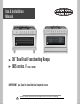
Use & Installation Manual 36” Dual Fuel Freestanding Range 965 series // F965 , F965NF IMPORTANT Save for local eletrical inspector’s use. Installer Write Product Serial Number Here before Installing. Serial Number can be found on the box or on the back of the unit.
Table of Contents Table of Contents.................................................................................................................2 Safety Requirements ...............................................................................................................3 Ventilation Requirements.......................................................................................................10 Gas Supply Requirements..........................................................................
Safety Requirements IMPORTANT SAFETY NOTICE READ ALL INSTRUCTION BEFORE INSTALLING AND OPERATING THIS APPLIANCE We have provided many important safety messages in this manual and on your appliance. Always read and obey all safety messages. This is the safety alert symbol. This symbol alerts you to potential hazards that can kill or hurt you and others. All safety messages will follow the safety alert symbol and either the word “DANGER” or “WARNING.
If the information in this manual is not followed exactly, a fire or explosion may result causing property damage, personal injury or death. • FOR YOUR SAFETY: - Do not store or use gasoline or other flammable vapors and liquids in the vicinity of this or any other appliance. • WHAT TO DO IF YOU SMELL GAS: - Do not try to light any appliance. - Do not touch any electrical switch; do not use any phone in your building. - Immediately call your gas supplier from a neighbor’s phone.
• Do not repair or replace any part of the appliance unless specifically recommended in the manuals. All other servicing should be done only by a qualified technician. This may reduce the risk of personal injury and damage to the appliance. • Proper Installation – The range, when installed, must be electrically grounded in accordance with local codes or, in the absence of local codes, with the National Electrical Code, ANSI/NFPA 70.
• Maintenance – Keep range area clear and free from combustible materials, gasoline, and other flammable vapors and liquids. • Storage in or on the Range – Flammable materials should not be stored in an oven or near surface units. Do not store items of interest to children in the cabinets above the appliance or on the backguard of a range. Children should not be left alone or unattended in the area where appliance is in use. Do not allow children to climb or play around the appliance.
• When heating fat or grease, watch it closely. Fat or grease may catch fire if allowed to become too hot. • Use only dry potholders. Moist or damp potholders on hot surfaces may result in burns from steam. Do not let potholders touch hot heating elements, the flame or burners. Do not use a towel or other bulky cloth instead of a potholder. • Do not heat unopened food containers. Buildup of pressure may cause the container to burst and result in injury.
• Do not use aluminum foil to line any part of the appliance. Use aluminum foil only to cover food during cooking. Improper installation of these liners may result in risk of electric shock or fire. • Only certain types of glass, glass/ceramic, ceramic, earthenware, or other glazed utensils are suitable for appliance service without breaking due to the sudden change in temperature. Check the manufacturer’s recommendations for appliance use. • Do not use decorative surface burner covers.
TO REDUCE THE RISK OF TIPPING OF THE RANGE, THE RANGE MUST BE SECURED BY PROPERLY INSTALLED ANTI-TIP DEVICES. TO CHECK IF THE DEVICES ARE INSTALLED PROPERLY, SLIDE RANGE FORWARD, LOOK FOR ANTI-TIP DEVICE SECURELY ATTACHED TO WALL. • The range will not tip during normal use. However, the range can tip if you apply too much force or weight to the open door without having the anti-tip bracket fastened down properly. TIP OVER HAZARD A child or adult can tip the range and be killed.
Ventilation Requirements The range should have proper ventilation in order to keep the unit operating properly and maintain the temperature of immediate surroundings within safe limits. Check your local building codes as they may vary from the general rules outlined in this guide. It is recommended that a hood be installed above the range that is rated no less than 400 CFM. This will provide adequate ventilation for this range.
• To eliminate the risk of burns or fire by • Avoid placing cabinetry directly above reaching over heated surface units, cabinet the appliance when possible. If cabinetry is storage space located above the surface units used above the cooking surface, use cabinets should be avoided. If cabinet storage is to be no more than 13″ deep.
MOBILE HOME – ADDITIONAL INSTALLATION REQUIREMENTS • The installation of this range must conform to the Manufactured Home Construction and Safety Standard, Title 24 CFR, Part 3280 (formerly the Federal Standard for Mobile Home Construction and Safety, Title 24, HUD Part 280). When such standard is not applicable, use the Standard for Manufactured Home Installations, ANSI A225.1/NFPA 501A or with local codes.
Gas Supply Requirements EXPLOSION HAZARD • Observe all governing codes and ordinances. Use a new CSA International approved gas IMPORTANT: This installation must conform supply line. with all local codes and ordinances. In the Install a shut-off valve. absence of local codes, installation must Securely tighten all gas connections. conform with American National Standard, If connected to LP, have a qualified person National Fuel Gas Code ANSI Z223.
GAS SUPPLY LINE: − Provide a gas supply line of ¾" (1.9 cm) rigid pipe to the range location. A smaller size pipe on longer runs may result in insufficient gas supply. Pipejoint compounds that resist the action of LP gas must be used. Do not use TEFLON®† tape. With LP gas, piping or tubing size must be ½" (1.3 cm) minimum. Usually, LP gas suppliers Figure 2 determine the size and materials used in the system.
RIGID PIPE CONNECTION: − The rigid pipe connection requires a combination of pipe fittings to obtain an in-line connection to the range. The rigid pipe must be level with the range connection. All strains must be removed from the supply and fuel lines so range will be level and in line. (See Figure 4) Figure 4 MUST INCLUDE A SHUTOFF VALVE: − The supply line must be equipped with a manual shutoff valve.
NATURAL GAS BURNER Auxiliary Semi-Rapid Rapid Triple Ring POSITION NATURAL GAS NOZZLES NOZZLE MINIMUM Front Right Rear Left & Right Front Left Center MAXIMUM DIAMETER PRESSURE PRESSURE 1 x 1.10 2 x 1.29 1 x 1.45 5 x 0.99 4” 4” 4” 4” 14” 14” 14” 14” LIQUID PETROLEUM (LP) GAS BURNER Auxiliary Semi-Rapid Rapid Triple Ring • LIQUID PERTROLEUM (LP) GAS NOZZLES POSITION NOZZLE MINIMUM Front Right Rear Left & Right Front Left Center MAXIMUM DIAMETER PRESSURE PRESSURE 1 x 0.70 2 x 0.80 1 x 0.
Electrical Requirements instructions in the “Electrical Connection” section. If you wish to install this appliance directly to the main (without a plug), it must be installed by a qualified service technician. Electrical Shock Hazard • Do not use an extension cord. 2-prong adapter or an extension cord. If a 2- Failure to follow these instructions can prong wall receptacle is the only available result in death, fire, or electrical shock.
Advance Preparation Tools and Parts Gather the required tools and parts before starting installation. Read and follow the instructions provided with any tools listed here. ■ Tape measure ■ Phillips screwdriver PARTS SUPPLIED: ■ Flat blade screwdriver Check that all parts are included.
Range Dimensions • Avoid placing cabinetry directly above the appliance when possible. If cabinetry is used above the cooking surface, use cabinets no more than 13″ deep. Make sure the wall coverings, countertop and cabinets around the appliance can withstand heat up to 200º F (93°C) generated by the appliance. (See Figures 1 and 6) • Cabinet opening dimensions that are shown must be used. Given dimensions are minimum clearances.
Unpack Range Install Leveling Feet and Back Panel Excessive Weight Hazard Tip Over Hazard A child or adult can tip the range and be killed. Use two or more people to move and install range. Failure to follow these instructions can result in death or serious burns to children and adults. 1. Remove shipping materials from the range. DO NOT remove protective film covering the appliance. 6. Install the leveling feet one at a time. The leveling feet can be found in one of the boxes that was inside the oven.
Install Anti-Tip Device (Chain) Tip Over Hazard A child or adult can tip the range and be killed. Connect anti-tip bracket to rear range foot. Reconnect the anti-tip bracket, if the range is moved. Failure to follow these instructions can result in death or serious burns to children and adults. The range is supplied with an antitilting chain to prevent the appliance from tilting forward and accidental damage to the gas pipe.
Installation Instructions Gas Connection Explosion Hazard Use a new CSA International approved gas supply line. Install a shut-off valve. Securely tighten all gas connections. If connected to LP, have a qualified person make sure gas pressure does not exceed 14" (36 cm) water column. Examples of a qualified person include: licensed heating personnel, authorized gas company personnel, and authorized service personnel. Failure to do so can result in death, explosion, or fire.
BURNER Auxiliary Semi-Rapid Rapid Triple Ring POSITION NATURAL GAS NOZZLES NOZZLE MINIMUM Front Right Rear Left & Right Front Left Center MAXIMUM DIAMETER PRESSURE PRESSURE 1 x 1.10 2 x 1.29 1 x 1.45 5 x 0.99 4” 4” 4” 4” 14” 14” 14” 14” • If the appliance is converted for liquid pretroleum (LP) gas, the LP gas supply is required to provide a minimum of 10” to a maximum of 14” water column to the cooktop regulator.
Figure 12 5) Once regulator is in place, open the shutoff valve in the gas supply line. Wait a few minutes for gas to move through the gas line. 6) After connecting the appliance to the gas supply, make sure all burners knobs are in the OFF position and check the system for leaks with a manometer. If a manometer is not available, turn on the gas supply and use a liquid leak detector (or soap and water) at all joints and connections to check for leaks.
• Isolate the range from the gas supply piping system by closing its individual manual shutoff valve during any pressure testing of the gas supply piping system at test pressures equal to or less than 1/2 psi (3.5 kPa or 14" water column). ASSEMBLY OF THE BURNERS The electrode of the electronic ignition system is positioned above the surface of the burner base. Do not remove a burner cap or touch the electrode of a burner while another is turned on. Damage or electrical shock may occur. 1.
Liquefied Petroleum (Propane) Gas Conversion Failure to make the appropriate conversion can result in serious personal injury and property damage. The conversion must be performed by a qualified service technician in accordance with the kit instructions and all local codes and requirements. Failure to follow instructions could result in serious injury or property damage. The qualified agency performing this work assumes responsibility for the conversion.
1) Unscrew the regulator cap with the wrench. (See Figure 15) 4) Reverse the retainer pin and put back into the regulator cap. This is how the regulator pin looks for LP gas usage. (See Figure 18) Figure 15 2) This is how the retainer pin looks for Natural Gas usage. (See Figure 16) Figure 18 5) Screw the regulator cap back into the regulator and re-attach the regulator to the nipple and flare union. (See Figures 12 and 19) Figure 16 3) Remove the retainer pin.
B. CHANGE BURNER NOZZLES INSTALLATION TIP: First remove all nozzles and then start replacing them. This will help to prevent the possibility that some may not be replaced. 1) Remove the burner grates, burner caps and burner heads. 2) Using a 7mm nut driver, remove the burner nozzles.
C. ADJUST BURNER FLAMES 4) To adjust the flame, remove the knobs; 1) Turn all burners on highest setting and insert a screwdriver through the access check the flames. They should be blue hole in valve shaft as shown. Make the in color and may have some yellow adjustment by slowly turning the screw tipping at the ends of the flame when until flame appearance is correct. (See using LP gas.
TESTING FLAME STABILITY Test 1——Turn the knob from “HI” to “LO” quickly. If the upper row of flames goes out at this setting, increase the flame size and test again. Test 2——With the burner on “LO”, open and close the cabinet door under the range. If the flame is extinguished by the air currents created by the door movement, increase the flame height and test again. D. FLAME RE-CHECK After the adjustment is made, turn all burners off. Ignite each burner individually.
Electrical Connection Electrical Shock Hazard Do not use an adapter. Do not use an extension cord. Failure to follow these instructions can result in death, fire, or electrical shock. Electrical connection must be performed by a qualified service technician in accordance with the kit instructions and all local codes and requirements. • This appliance is not supplied with a plug and needs to be connected directly to the electrical mains.
BEFORE MAKING THE ELECTRICAL CONNECTION, MAKE SURE THAT: • The safety circuit-breaker and the electrical system are able to with stand the load of the appliance. See rating label on back of range. • Rating plate is located on back of range should you need to verify any of the electrical requirements. • The power supply system has a ground connection in good working order in accordance with the regulations in force. • The electrical socket is easily accessible with the appliance installed.
3) The two black wires can be connected to the electrical main wires of the home in one of the following three configurations: • Configuration 1: L1 to L1 and L2 to L2 • Configuration 2: L1 to L1 and L2 to L3 • Configuration 3: L1 to L2 and L2 to L3 Figure 24 4) Never use reductions, shunts, or adaptors which can cause overheating or burning. 5) After carrying out the connection to the mains, check that the supplying cable does not come into contact with parts subject to heating.
Using the Cooktop Flame Size • For most cooking, start on the highest control setting and then turn to a lower one to complete the process. The size and type of utensil used and the amount of food being cooked will influence the setting needed for cooking. • For deep fat frying, use a thermometer and adjust the surface control knob accordingly. If the fat is too cool, the food will absorb the fat and be greasy. If the fat is too hot, the food will brown so quickly that the center will be undercooked.
Location of the Burners 1. Auxiliary burner (Front right) - 5,000 BTU 2. Rapid burner ( Front left) – 8,500 BTU 3. Semi-rapid burners (Rear left and right) – 7,000 BTU 4. Triple-ring burner – (Center) 18,000 BTU Figure 26 Placement of Burner Heads and Caps 1) Place a burner cap on each burner head, matching the cap size to the 4) Do not service the sealed burner yourself. head size. The cap for each burner has an inner locating ring which centers the cap correctly on the burner head.
Cooktop Using Pots and Pans Do not place plastic items such as salt and pepper shakers, spoon holders or plastic wrappings on top of the appliance when it is in use. These items could melt or ignite. Potholders, towels or wood spoons could catch fire if placed too close to a flame. Note: Always use a utensil for its intended purpose. Follow manufacturer’s instructions. Some utensils were not made to be used in the oven or on the cooking surface.
Setting Cooktop Controls SYMBOLS Figure 30 IGNITION AND OPERATION OF THE GAS BURNERS 1. To obtain a flame more easily, light the 5. If the burner fails to ignite, wait one burner before placing a cooking utensil minute for the gas to dissipate before on the burner grate. attempting to reignite. At this moment it is possible to adjust the flame 2. To light a burner, press the knob of the burner fully down and turn it counter- intensity by rotating the knob counterclockwise to the desired position.
Oven Cooking Setting Oven Clock and Timer Figure 31 DIGITAL CLOCK COOKING WITH THE TIMER This model has a digital display 24 hour clock By selecting the desired end time, cooking with 3 control buttons. When first connected to time, temperature and cooking mode you can power (or after a power outage) the screen will set the oven to cook your dish automatically. display ’12:00’ and the bar above the (See Figure 31) symbol will flash.
Setting Oven Controls Figure 32 Figure 33 Selection of cooking temperature is carried out by turning the knob clockwise to the required temperature. The warning light will illuminate during the heating process. Once the oven reaches desired temperature, the light will go out. Regular flashing means that the oven temperature is being maintained at the programmed level. OVEN LIGHT INDICATOR The lamp of the oven is on. During oven operation the lamp will always remain on.
DELICATE COOKING (Lower element and Fan) THERMOSTAT SELECTOR SWITCH FROM 60° C (140° F) TO MAX Ideal for pastries and cakes with wet covering and little sugar and damp desserts in moulds. Excellent results can also be achieved in completing cooking at the bottom and with dishes requiring heat in the lower area in particular. The plate is best inserted at bottom level. UPPER ELEMENT COOKING THERMOSTAT SELECTOR SWITCH FROM 60° C (140° F) TO MAX This is best used to brown select dishes at the end of cooking.
DEFROST (Bottom fan) All types of food can be defrosted by circulating air at room temperature: cakes, cream, fruit, etc. For foods such as: meat, fish, and bread you will want to set the fan temperature to 175-200° C (347-392° F).
Cooking Instructions Setting: Traditional Cooking (add time for preheat) Convection Cooking (add time for preheat) Setting: Grill Cooking Food: Rack Level (See Figure 33) 2-3 2-3 Temperature (Fahrenheit): 410-450 410-450 Time (mins): 2 2 2 2 2 1 2 1-2 350-400 410-460 340-400 340-400 340-400 280-340 340-400 340-400 Pizza Short Pastry Fruit Cake Browning Lasagna Oven-Baked Pasta Roast Veal Beef Pork Chicken Duck Goose/Turkey Lamb Fish 1-2 1-2 1-2 3-4 2-3 2 410-450 340-400 340-400 140 375-410 375-
Care and Cleaning ELECTRICAL SHOCK HAZARD BURN HAZARD To avoid possible burns use care when cleaning the appliance. DO NOT attempt to clean the appliance whenever the oven or burner heads are still hot. To avoid possible burns DO NOT attempt any of the following cleaning instructions before turning OFF ALL of the surface burners and allowing them to cool. IMPORTANT: Always follow label instructions on cleaning products. • Control Knobs − For general cleaning, use hot, soapy water and a cloth.
• Burner Caps − To clean the burner caps, lift the burner cap off the burner head. Clean heavy soils with an absorbent cloth. − Rinse with a clean, damp cloth and immediately thoroughly dry including the bottom and inside of the cap. − Do not use harsh abrasive cleaners. They can scratch the cap. − DO NOT PUT BURNER UNITS IN THE DISHWASHER • Burner Heads − The holes in the burners of your appliance MUST be kept clean at all times for proper ignition and a complete, even flame.
• Cleaning Interior Lower Grill Element − To remove the element, support one side with your hand while removing the retainer with the other. − When cleaning, make sure not to apply excessive force on the element as it is fragile. − Reposition the element and secure the retainer back in place. − DO NOT use the oven with the grill element hanging down – it must be repositioned after cleaning. • Oven Door Exterior − Use a glass cleaner and a soft cloth or sponge.
• Changing the Interior Oven Light Bulb ELECTRICAL SHOCK HAZARD − Ensure that the appliance is switched off before replacing the lamp to avoid possible electric shock. − Remove the glass cover by turning counter clockwise.
Solutions to Common Problems IMPORTANT Before calling for service, review this list. It may save you both time and expense. This list includes common experiences that are not the result of defective workmanship or material in your appliance. Electrical Shock Hazard Plug into a grounded 3 prong outlet. Do not remove ground prong. Do not use an adapter. Do not use an extension cord. Failure to follow these instructions can result in death, fire, or electrical shock.
■ Are the burner ports clogged? See “Care and Cleaning” section. SURFACE BURNERS ARE UNEVEN, YELLOW AND/OR NOISY ■ Are the burner ports clogged? See “Care and Cleaning” section. ■ Are the burner caps positioned properly? See “Placement of Burner Heads and Caps” section. ■ Is propane gas being used? The range may have been converted improperly. Contact a qualified service technician. See “Liquid Petroleum (Propane) Gas Conversion” section. SURFACE BURNER MAKES POPPING NOISES ■ Is the burner wet? Let it dry.
COOLING FAN RUNS DURING BAKING AND BROILING ■ It is normal for the fan to automatically run while the oven is in use and for some time after to cool. OVEN TEMPERATURE TOO HIGH OR TOO LOW ■ Was the oven preheated? See “Cooking Instructions” section. ■ Are the racks positioned properly? See “Cooking Instructions” section. ■ Is there proper air circulation around bakeware? See “Cooking Instructions” section. ■ Is the batter evenly distributed in the pan? Check that batter is level in the pan.
■ Gas valve - The valve is not open. Make sure the valve is completely open. ■ Gas pipe - There may be air in the gas pipe. Ignite repeatedly until flame catches. ■ Burner cap − The burner cap is not placed correctly. o − Replace the burner cap. Some holes in the lid are stocked. o Clean the holes of the lid. ■ Spark pin - The spark pin is wet or contaminated by the food. Clean and dry the spark pin.. ■ Gas connecting pipes - The gas connecting pipes are stocked or squashed.
WARRANTY AND SERVICE For full warranty details on this product please visit: http://www.cosmoappliances.com/warranty TO RECEIVE WARRANTY SERVICE, YOUR PRODUCT MUST BE REGISTERED. TO REGISTER, VISIT: WWW.COSMOAPPLIANCES.