GAS RANGE COS-GRC304KB COS-GRC366KB SLIDE-IN RANGE INSTALLATION INSTRUCTIONS IMPORTANT: READ AND SAVE THESE INSTRUCTIONS. FOR RESIDENTIAL USE ONLY. INSTALLER: PLEASE LEAVE THESE INSTRUCTIONS WITH THIS UNIT FOR THE OWNER. OWNER: PLEASE RETAIN THESE INSTRUCTIONS FOR FUTURE REFERENCE. Rev.24.
THANK YOU FOR YOUR PURCHASE Thank you for your purchase. We know that you have many brands and products to choose from and we are honored to know that you have decided to take one of our products into your home and hope that you enjoy it. COSMO Appliances are designed according to the strictest safety and performance standard for the North American market. We follow the most advanced manufacturing philosophy. Each appliance leaves the factory after thorough quality inspection and testing.
TABLE OF CONTENTS RANGE SAFETY.................................................................................................... 4 Anti-tip Device ........................................................................................................... 7 INSTALLATION REQUIREMENTS ........................................................................ 8 Tools and Parts .......................................................................................................... 8 Location Requirements .....
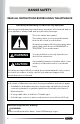
RANGE SAFETY READ ALL INSTRUCTIONS BEFORE USING THE APPLIANCE Your safety and the safety of others are very important. We have provided many important safety messages in this manual and on your appliance. Always read and obey all safety messages. This is the safety alert symbol. This symbol alerts you to potential hazards that can kill or hurt you and others. All safety messages will follow the safety alert symbol and either the word "WARNING" or "CAUTION.
WARNING FIRE AND EXPLOSION HAZARD If the information in this manual is not followed exactly, a fire or explosion may result causing property damage, personal injury or death. • Do not store or use gasoline or other flammable vapors and liquids in the vicinity of this or any other appliance. • WHAT TO DO IF YOU SMELL GAS - Do not try to light any appliance. - Do not touch any electrical switch. - Do not use any phone in your building. - Clear the room, building, or area of all occupants.
WARNING • Gas leaks cannot always be detected by smell. Gas suppliers recommend that you use a gas detector approved by UL or CSA. For more information, contact your gas supplier. • Do not install a ventilation system that blows air downward toward this cooking appliance. This type of ventilation system may cause ignition and combustion problems with this cooking appliance resulting in personal injury or unintended operation. • This appliance is intended for normal residential use.
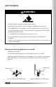
ANTI-TIP DEVICE WARNING TIP OVER HAZARD • A child or adult can tip the range and be killed. • Install anti-tip bracket to floor or wall per installation instructions. • Slide range back so rear range foot is engaged in the slot of the floormounting anti-tip bracket or rear range pin is engaged under the wallmounting anti-tip bracket. • Re-engage the anti-tip bracket if range is moved. • Do not operate the range without anti-tip bracket installed and engaged.
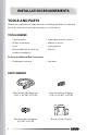
INSTALLATION REQUIREMENTS TOOLS AND PARTS Gather the required tools and parts before starting installation. Read and follow the instructions provided with any tools listed here.
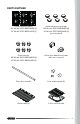
PARTS SUPPLIED Surface burner grates 30" Model: COS-GRC304KB (2) 36" Model: COS-GRC366KB (3) Surface burners and caps 30" Model: COS-GRC304KB (4) 36" Model: COS-GRC366KB (6) (pre-installed) Control knobs 30" Model: COS-GRC304KB (4) 36" Model: COS-GRC366KB (6) Oven door handle end caps with set screws (2) Oven door handle Rear rubber pads (2) Oven racks (2) 2-Piece broiler pan 9
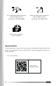
Floor-mounting anti-tip bracket with mounting screws 30" Model: COS-GRC304KB Wall-mounting anti-tip bracket with mounting screws 36" Model: COS-GRC366KB Gas pressure regulator (pre-installed) Optional Parts To purchase these or any other accessories or replacement parts, please visit www.cosmoappliances.com or reference the contact information at the end of this manual.
LOCATION REQUIREMENTS IMPORTANT: Observe all governing codes and ordinances. Do not obstruct flow of combustion and ventilation air. • It is the installer's responsibility to comply with installation clearances specified on the model/serial/rating plate. The model/serial/rating plate is located behind the oven door on the oven frame, and also on the back panel of the range. Rating Plate • The range should be located for convenient use in the kitchen.
• Proper gas supply connection must be available. See "Gas Supply Requirements" section. • Contact a qualified floor covering installer to check that the floor covering can withstand at least 167°F (75°C). • Use an insulated pad or 1/4" (0.64 cm) plywood under range if installing range over carpeting. IMPORTANT: To avoid damage to your cabinets, check with your builder or cabinet supplier to make sure that the materials used will not discolor, delaminate, or sustain other damage.
PRODUCT SPECIFICATIONS Model COS-GRC304KB Description 30" Gas Range Oven Capacity 4.8 cu. ft. Electrical Requirements 120VAC 60Hz Ratings Refer to Rating Plate Exterior Dimensions (WxDxH) 29 ⁷⁄₈" x 29 ³⁄₄" x 37 ¹⁄₄" (75.9 x 75.5 x 94.6 cm) Height to Cooking Surface 37 ¹⁄₈" - 38 ¹⁄₈" (94.3 - 96.9 cm) Net Weight 185 lb (84.0 kg) Model COS-GRC366KB Description 36" Gas Range Oven Capacity 6.0 cu. ft.
PRODUCT DIMENSIONS Your model may appear different from the model depicted. Dimensions given are maximum dimensions. COS-GRC304KB 28 ¹⁄₄ in (71.8 cm) 29 ⁷⁄₈ in (75.9 cm) 37 ¹⁄₄ in (94.6 cm) 27 in (68.6 cm) 48 ⁵⁄₈ in (123.5 cm) Door fully open 29 ⁷⁄₈ in (75.9 cm) 29 ³⁄₄ in (75.5 cm) 36 ¹⁵⁄₁₆ in (93.8 cm) 35 ¹³/₁₆ in (90.9 cm) 24 ³⁄₄ in (62.8 cm) NOTE: • Range can be raised approximately 1" (2.5 cm) by adjusting the leveling legs.
COS-GRC366KB 27 ⁵⁄₁₆ in (69.3cm) 35 ⁷⁄₈ in (91.1 cm) 37 ¹⁄₈ in (94.3 cm) 27 in (68.6 cm) 48 ⁵⁄₈ in (123.5 cm) Door fully open 35 ⁷⁄₈ in (91.1 cm) 29 ⁹⁄₁₆ in (75.1 cm) 37 ¹⁄₈ in (94.3 cm) 36 in (91.4 cm) 24 ³⁄₄ in (62.8 cm) NOTE: • Range can be raised approximately 3" (7.6 cm) by adjusting the leveling legs.
CLEARANCES IMPORTANT: Some cabinet and building materials are not designed to withstand the heat produced by the oven for baking and self-cleaning. Check with your builder or cabinet supplier to make sure that the materials used will not discolor, delaminate or sustain other damage. GIVEN DIMENSIONS ARE MINIMUM CLEARANCES. 13 in (33 cm) Overhead Cabinet Depth A 18 in (45.7 cm) 6 in (15.2 cm) to left wall 30 in (76.2 cm) 6 in (15.2 cm) to right wall 36 in (91.
NOTE: • 30" (76.2 cm) minimum clearance between cooking surface and bottom of the overhead cabinet. • 18" (45.7 cm) minimum clearance from upper cabinet to countertop on either side of unit. • Island Installations: Maintain 6" (15.2 cm) minimum clearance from cutout to back and side edges of countertop. POWER SUPPLY LOCATION IMPORTANT: An electrical outlet in the floor, may be either recessed or surface mounted, but an electrical outlet in the wall must be recessed to make the connection.
VENTING REQUIREMENTS IMPORTANT: This range must be exhausted outdoors unless you are using ductless venting. Observe all governing codes and ordinances. Do not obstruct flow of combustion and ventilation air. • Do not terminate the vent system in an attic or other enclosed area. • Use an approved vent cap for proper performance. If an alternate wall or roof cap is used, be certain the cap size is not reduced and that it has a backdraft damper.
ELECTRICAL REQUIREMENTS WARNING ELECTRICAL SHOCK HAZARD • Do not use an extension cord with this appliance. • Remove house fuse or open circuit breaker before beginning installation. ELECTRICAL GROUNDING INSTRUCTIONS • The power cord of this appliance is equipped with a three-prong (grounding) plug which plugs into a standard three-prong grounding wall receptacle to minimize the possibility of electric shock hazard from this appliance.
ELECTRICAL CONNECTION WARNING: Improper connection of the equipment-grounding conductor can result in a risk of electric shock. Check with a qualified electrician or service technician if you are in doubt as to whether the appliance is properly grounded. Do not modify the power supply cord plug. If it will not fit the outlet, have a proper outlet installed by a qualified electrician.
GAS SUPPLY REQUIREMENTS WARNING FIRE AND EXPLOSION HAZARD • Use a new CSA International approved gas supply line. • Install a shut-off valve. • Securely tighten all gas connections. • If connected to LP, have a qualified person make sure gas pressure does not exceed the maximum pressure listed in this section. • Examples of a qualified person include: - licensed heating personnel - authorized gas company personnel - authorized service personnel • Failure to do so can result in death, explosion or fire.
TYPE OF GAS This range has been design-certified according to ANSI Z21.1a, latest edition for use with natural gas or, after proper conversion, for use with Propane (LP) gas. Natural Gas This range is factory-set for use with Natural gas (NG). The model/serial/rating plate located on the back panel of the range has information on the types of gas that can be used. If the types of gas listed do not include the type of gas available, check with the local gas supplier.
• A 1/2" (1.3 cm) male pipe thread is needed for connection to the female pipe threads of the inlet to the appliance pressure regulator. • Do not kink or damage the flexible metal tubing when moving the range. Rigid Pipe Connection • Since the range must be pulled away from the installation space to provide access to the gas regulator connections, and because hard piping restricts movement of the range, the range can only be installed using a CSA International-certified flexible metal appliance connector.
Burner Input Requirements Input ratings shown on the model/serial/rating plate are for elevations up to 2,000 ft (609.6 m). For elevations above 2,000 ft (609.6 m), ratings are reduced at a rate of 4% for each 1,000 ft (304.8 m) above sea level (not applicable for Canada). GAS SUPPLY PRESSURE TESTING Gas supply pressure for testing regulator must be at least 1" (2.5 cm) water column pressure above the manifold pressure shown on the model/serial/rating plate. Line pressure testing above 0.
INSTALLATION INSTRUCTIONS IMPORTANT: This appliance shall be installed only by authorized persons and in accordance with the manufacturer's installation instructions, local gas fitting regulations, municipal building codes, electrical wiring regulations, local water supply regulations. REMOVE OLD APPLIANCE WARNING FIRE AND EXPLOSION HAZARD If the information in this manual is not followed exactly, a fire or explosion may result causing property damage, personal injury or death.
WARNING ELECTRICAL SHOCK HAZARD • Remove house fuse or open circuit breaker to disconnect power before servicing. Failure to do so can result in death, fire, or electrical shock. WARNING EXCESSIVE WEIGHT HAZARD • Use two or more people to move and install range. Failure to do so can result in back or other injury.
UNPACK RANGE WARNING EXCESSIVE WEIGHT HAZARD • Use two or more people to move and install range. Failure to do so can result in back or other injury. 1. Remove all tape and packaging materials. Check for film on stainless steel parts, padding/spacers on and around door and face of oven, cardboard and plastic on and around racks, etc. Failure to remove packaging materials could result in damage to the appliance. Do not dispose of anything until the installation is complete.
INSTALL REAR RUBBER PADS (OPTIONAL) 1. Locate the rubber pads and screws from the parts bag. 2. Install the rubber pads to the back panel of range. Do not overtighten.
INSTALL ANTI-TIP DEVICE WARNING TIP OVER HAZARD • A child or adult can tip the range and be killed. • Install anti-tip bracket to floor or wall per installation instructions. • Slide range back so rear range foot is engaged in the slot of the floormounting anti-tip bracket or rear range pin is engaged under the wallmounting anti-tip bracket. • Re-engage the anti-tip bracket if range is moved. • Do not operate the range without anti-tip bracket installed and engaged.
FLOOR-MOUNTING ANTI-TIP BRACKET (30" MODEL: COS-GRC304KB ONLY) Anti-tip bracket Range foot 1. Locate and remove the anti-tip bracket and mounting screws from the parts bag. 2. Locate the preferred location for installation of the anti-tip bracket and mark the location of the screw holes. Bracket may be installed at either the back-left or back-right corner of the installation space. NOTE: • Only one anti-tip bracket needs installed. ³/₁₆" (4.
Rear rubber pad ¹³⁄₁₆" (20.0 mm) Rear range foot Anti-tip bracket 1 ³⁄₄" (43.6 mm) 3. Follow the instructions specific to your construction. Wood Construction • Drill an appropriate hole where screws are to be located. Screw must enter wood. Masonry Construction • Due to the variety of masonry materials that may be present at installation site, hardware is not provided for attaching the anti-tip bracket to masonry.
4. Secure anti-tip bracket to floor with the screws provided. WALL-MOUNTING ANTI-TIP BRACKET (36" MODEL: COS-GRC366KB ONLY) Anti-tip bracket Pin 1. Locate and remove the anti-tip bracket and mounting screws from the parts bag.
2. Locate the pin on the back of the range near the bottom corner. ⁵⁄₈" (16.5 mm) Pin 3" (76.1 mm) Leveling Leg 3. Locate the preferred location on the wall for installation of the anti-tip bracket. The pin must be engaged under the arm of anti-tip bracket when sliding range into final position. • The top of the anti-tip bracket should be at least 4 ¹⁄₄" (107 mm) above floor with the leveling legs fully contracted. • The edge of the anti-tip bracket arm should be between 3" (76.1 mm) and 3 ⁹⁄₁₆" (90.
Rear Rubber Pad ¹³⁄₁₆" (20.0 mm) 3 ¹⁄₈" (80 mm) 1 ¹⁄₂" (38.1 mm) 2 ¹⁄₈" (53.8 mm) 4. Mark the location of the anti-tip bracket screw holes on the wall. 5. Drill an appropriate hole where screws are to be located. Screw must enter wood. 6. Secure anti-tip bracket to wall with the screws provided.
INSTALL/REMOVE CONTROL KNOBS Be very careful not to scratch the surface of the unit. The appearance of the knobs may vary from what are shown below.
Installing the Control Knob 1. Hold the knob in an upright position with the OFF marking facing upward. Observe the open part centered on the back of the knob. 2. Place and align the open part on the back of the knob over the control stem that is sticking out of the control panel. 3. Press the knob onto the stem, and make sure the knob is in the OFF position. Removing the Control Knob 1. Pull the knob straight off the stem.
GAS CONNECTION WARNING FIRE AND EXPLOSION HAZARD • Use a new CSA International approved gas supply line. • Install a shut-off valve. • Securely tighten all gas connections. • If connected to LP, have a qualified person make sure gas pressure does not exceed the maximum pressure listed in the "Gas Supply Requirement" section.
TYPICAL FLEXIBLE CONNECTION Gas pressure regulator Flexible connector (6 ft. max.) Gas shut-off valve 1/2" Adapter 1/2" Adapter 1/2" or 1/4" Gas pipe Gas flow into range 1. Make sure a manual gas line shut-off valve is installed in an easily accessible location. 2. Turn manual shut-off valve to the closed position. 3. Unplug range or disconnect power. 4. If present, remove the plastic cap at the regulator inlet on the back of the range. IMPORTANT: Do not remove the gas pressure regulator.
5. Apply pipe-joint compound made for use with NG/LP gas to the smaller thread ends of the flare union adapters. 6. Attach male 1/2" flare union adapter to the 1/2" NPT internal thread at the regulator inlet with a wrench using no more than 15 ft-lbs of torque. Use a backup wrench on the regulator fitting to avoid damage. NOTE: • Do not make connections to the gas regulator too tight. Overtightening may crack the regulator resulting in a gas leak and possible fire or explosion. 7.
CONVERT TO LP GAS (OPTIONAL) This range is shipped from the factory set up to use natural gas. It can be converted to operate on propane gas (LP) by a qualified service technician. The LP conversion kit is sold separately. The conversion to LP requires all surface and oven burner gas orifices to be changed. In addition, the gas pressure regulator must also be adjusted for LP. See "Gas Conversion" section for detailed instructions.
COMPLETE INSTALLATION ELECTRICAL CONNECTION WARNING ELECTRICAL SHOCK HAZARD • Remove house fuse or open circuit breaker to disconnect power before servicing. • Plug into a grounded 3-prong outlet. • Do not use an adapter or an extension cord. • Failure to do so can result in death, fire, or electrical shock. IMPORTANT: • The power cord of this appliance is equipped with a three-prong (grounding) plug which plugs into a standard three-prong grounding wall receptacle.
PLACEMENT AND LEVELING RANGE WARNING EXCESSIVE WEIGHT HAZARD • Use two or more people to move and install range. Failure to do so can result in back or other injury. CAUTION LACERATION, FOREIGN OBJECT, CRUSH HAZARD • When installing, moving, or servicing any appliance, wear proper protective equipment, including cut resistant gloves, steel-toed shoes, and safety glasses. IMPORTANT: • Do not lift by the oven door handle or control knobs.
1. Use tape measure to measure from the floor to the top of the countertop at all four corners of the installation space. 2. While range is still positioned outside the installation space, use a plier or wrench to adjust the leveling leg at each corner so that the distance from the floor to the underside of the cooktop edge matches the dimensions measured in the installation space. 3.
VERIFY ANTI-TIP BRACKET ENGAGEMENT Do not operate the range if its rear foot is not engaged in the slot of the floormounting anti-tip bracket or its rear pin is not engaged under the arm of wall-mounting anti-tip bracket. IMPORTANT: If the range is pulled away from the wall for any reason, always verify anti-tip bracket engagement again. 1. Place the outside of your foot against the bottom of the front panel to keep the range from moving, and then grasp the back of the range, as shown. 2.
REMOVING/ASSEMBLING OVEN DOOR For normal range use, it is not suggested to remove the oven door. However, if removal is necessary, make sure the oven is off and cool. NOTE: • The oven door is heavy. • If door is removed, confirm that door operates correctly and seals properly when reinstalled. If door gasket does not seal completely, heat escaping from around doors could ignite cabinetry. Removing Door 1. Fully open the oven door. 2.
Assembling Door 1. Firmly grasp both sides of the door. 2. With the door at the same angle as the removal position, which is approximately five degrees or 2-3 inches from being fully closed, seat the indentation of the hinge arms into the bottom edge of the hinge slots. The notch in the hinge arms must be fully seated into the bottom edge of the slots. IMPORTANT: Do not lift door by door handle. 3. Open the door fully.
Installing the Handle 1. Partially loosen the set screws in the handle end caps with the Hex key. Set screw for mounting fastener Set screw for handle 2. Attach handle end cap over each end of the handle, and slightly tighten the set screws for handle. 3. Place the handle on the door by fitting the handle end cap footprints over the mounting fasteners and tightening all set screws with the Hex key.
Removing the Handle 1. Locate the set screws for mounting fastener on the handle end caps. Set screws Set screw for mounting fastener 2. Loosen the set screw on one end with the Hex key while supporting the handle. Do not remove the set screw from the handle end cap. 3. Keep supporting the handle while loosening the set screw on the other handle end cap. 4. Remove the handle from the mounting fasteners on the door and set aside.
ASSEMBLING THE SURFACE BURNERS AND GRATES IMPORTANT: Do not operate the burners without all parts in place. 1. Check that all range controls are in the OFF position. 2. If the surface burner bases and caps are not already installed, remove them from package containing parts. 3. Align and place the burner bases and caps in the correct locations. COS-GRC304KB (30") C A. Rapid (Medium) D B. Super Rapid (Large) A C. Semi Rapid (Medium) B D. Auxiliary (Small) COS-GRC366KB (36") A.
NOTE: • Align notches in burner caps with pins in burner base. • Make sure the hole in the burner base is positioned over the igniter. • Burner caps should be level when properly positioned. If burner caps are not properly positioned, surface burners will not light. • The burner cap should not rock or wobble when properly aligned. Burner cap Correctly positioned Burner base Orifice holder Incorrectly positioned 4.
CHECKING OPERATION OF THE SURFACE BURNERS Cooktop burners use electronic igniters. When the cooktop control knob is turned to the ignite position, the system creates a spark to light the burner. All or some other cooktop burners will spark, but only the burner with the control knob turned to the ignite position will produce a flame. This sparking continues as long as the control knob is turned to the ignite position. STANDARD SURFACE BURNERS The appearance of the knobs may vary from what are shown below.
QUALITY OF FLAMES The combustion quality of the burner flames needs to be confirmed visually. Soft blue flames This is normal for natural gas. Yellow tips on outer cones This is normal for LP gas. Yellow flames This is abnormal for any gas operation. Call for service. If Burners Do Not Light Properly: 1. Turn cooktop control knob to the OFF position. 2. Check that the range is plugged into a grounded 3 prong outlet. Check that the circuit breaker has not tripped or the fuse has not blown. 3.
ABNORMAL OPERATION ANY OF THE FOLLOWING ARE CONSIDERED TO BE ANBORMAL OPERATION AND MAY REQUIRE SERVICING: • Yellow burner flames. • Sooting up of cooking utensils. • Burners not igniting properly. • Burners failing to remain lit. • Burners extinguished by oven door. • Gas valves, which are difficult to turn. IN CASE THE APPLIANCE FAILS TO OPERATE CORRECTLY, CONTACT THE AUTHORIZED SERVICE PROVIDE IN YOUR AREA. THE BURNERS REQUIRE NO REGULATION OF THE PRIMARY AIR.
CHECKING OPERATION OF THE OVEN Oven burners do not require any adjustment. NOTE: • Ensure door is closed, all packaging is removed, and oven is empty except for oven rack(s). To Check Bake Burner: 1. Keep the oven door closed. The oven burners will turn off when oven door is open. 2. Press or repeatedly to select Bake mode, and press START/OK. 3. Press/Hold to adjust bake temperature setting to 175°F while it is flashing, and press START/OK.
4. Press START/OK to skip cook time setting and start the oven. • After a couple minutes when the oven temperature reaches above 100°F, the temperature on the display will begin to rise and show the current oven temperature. • Confirm that display shows temperature increasing. 5. Allow Bake mode to continue until oven has preheated to 175°F. • Confirm that preheat signals when temperature is reached. • Open the oven door temporarily.
GAS CONVERSION WARNING FIRE AND EXPLOSION HAZARD • Use a new CSA International approved gas supply line and install a shut-off valve for new installations. • Securely tighten all gas connections. • If connected to LP, have a qualified person make sure gas pressure does not exceed the maximum pressure listed in the "Gas Supply Requirement" section.
This range is factory-set for use with Natural gas (NG). The Propane gas (LP) conversion kit is sold separately. To order LP conversion kit, see "Optional Parts" in the "Tools and Parts" section. IMPORTANT: Gas conversions must be done by a qualified service technician in accordance with the manufacturer's instructions and all codes and requirements of the authority having jurisdiction. The qualified agency performing this work assumes the gas conversion responsibility.
4. Locate gas pressure regulator at rear of range. Gas pressure regulator 5. Remove 2 screws near center of gas pressure regulator, and remove regulator cap. IMPORTANT: Do not remove the gas pressure regulator. Keep the sealing gasket in place on the gas pressure regulator.
6. Replace the regulator cap for correct fuel type being used. IMPORTANT: Keep and store the regulator cap that has just been replaced in case of re-installation with another gas. Sealing gasket Gas pressure regulator NOTE: • If converting to propane from natural gas, please apply a label sticker with "LP Converted" notice on or near the regulator cover. If converting back to natural gas from propane, please remove the sticker so others know the appliance is set to use natural gas.
NG/LP Orifice Chart for Surface and Oven Burners COS-GRC304KB (30") NG Orifice Size (mm) LP Orifice Size (mm) Rating (BTU/h) Front Left 1.56 1.10 12,000 Front Right 1.95 1.28 18,000 Rear Left 1.35 0.90 9,000 Rear Right 0.88 0.58 3,500 Oven Top 1.56 1.01 NG: 12,000 / LP: 10,000 Oven Bottom 1.90 1.18 18,500 Burner Placement 60 9,000 BTU NG: 1.35 LP: 0.90 3,500 BTU NG: 0.88 LP: 0.58 12,000 BTU NG: 1.56 LP: 1.10 18,000 BTU NG: 1.95 LP: 1.
NG/LP Orifice Chart for Surface and Oven Burners COS-GRC366KB (36") NG Orifice Size (mm) LP Orifice Size (mm) Rating (BTU/h) Front Left 1.50 1.10 12,000 Front Middle 1.88 1.28 18,000 Front Right 1.50 1.10 12,000 Rear Left 1.31 0.90 9,000 Rear Middle 1.50 1.10 12,000 Rear Right 1.31 0.90 9,000 Oven Top 1.62 1.01 NG: 13,500 / LP: 12,000 Oven Bottom 1.90 1.21 NG: 18,500 / LP: 16,000 Burner Placement 9,000 BTU NG: 1.31 LP: 0.90 12,000 BTU NG: 1.50 LP: 1.10 9,000 BTU NG: 1.
1. If installed, remove burner grates, burner caps, and burner bases. 2. Remove the existing orifices with a 9/32" (7 mm) nut driver. Orifice 3. Replace the orifices with the correct fuel type orifices. Gas orifices are stamped with a size number. Refer to the orifice chart earlier for correct NG and LP gas orifice sizes and proper placement. IMPORTANT: Keep and store the orifices that have just been replaced in case of re-installation with another gas. 090 Orifice Size (090 - Denotes 0.90 mm) 4.
CONVERT OVEN BURNERS This product cannot be converted to Natural gas (NG) or Propane gas (LP) by adjusting or tightening the oven orifices. The orifices must be replaced. To gain better access to the oven components, the oven door may be detached from the range. See "Removing/Assembling Oven Door" section. Tool Needed • 3/8" (9.5 mm) combination wrench Converting Broil Burner 1. Empty the oven. 2. Remove the 4 screws from broil burner baffle at the oven top. Screws 3.
7. Place broil burner gas inlet on broil orifice holder and align burner assembly with the top and the rear of the oven. Make sure igniter wire is properly inserted into rear hole. 8. Replace the screws on burner assembly. Burner gas inlet Orifice holder Converting Bake Burner 1. Lift and remove bake burner cover on the oven bottom. Screws Heat shield plate 2. Remove the screw in the middle of lower heat shield on the right, and pull out rear heat shield plate to unveil bake orifice holder. 3.
6. Place bake burner gas inlet on bake orifice holder and align burner with the oven. Make sure igniter wire is properly inserted into rear hole. Heat shield plate 7. Replace the screws on burner. 8. Replace the rear heat shield plate. 9. Replace the bake burner cover. Burner gas inlet Orifice holder ADJUST SURFACE BURNER VALVES Be very careful not to scratch the surface of the unit. Tool Needed • Slotted (flat-head) screwdriver 1.
2. Locate the adjustment screw of burner valve next to the stem. Stem Adjustment screw 3. Tighten the adjustment screw to the correct fuel type position. Adjustment screw NG – horizontal position LP – vertical position 4. Replace the knobs. See "Install/Remove Control Knobs" section. COMPLETE GAS CONVERSION 1. Open shut-off valve in the gas supply line. 2. Plug in range or reconnect power. 3.
IMPORTANT Do Not Return This Product To The Store If you have a problem with this product, please contact COSMO Customer Support at +1 (888) 784-3108 DATED PROOF OF PURCHASE, MODEL #, AND SERIAL # REQUIRED FOR WARRANTY SERVICE. IMPORTANT Ne pas Réexpédier ce Produit au Magasin Pour tout problème concernant ce produit, veuillez contacter le service des consommateurs Cosmo Customer Support au +1 (888) 784-3108 UNE PREUVE D’ACHAT DATEE EST REQUISE POUR BENEFICIER DE LA GARANTIE.
APPLIANCES Cosmo is constantly making efforts to improve the quality and performance of our products, so we may make changes to our appliances without updating this manual. Electronic version of this manual is available at: www.cosmoappliances.