Fig.1 Fig.2 Fig.3 Fig.4 Fig.
Fig.6 Fig.8 Fig.7 Fig.
Fig.10 Fig.11 Fig.12 Fig.13 A Fig.14 B Fig.
Fig.16 Fig.17 Fig.18 Fig.19 Fig.20 Fig.21 Fig.22 Fig.23 Fig.
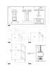
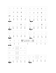
Fig.25 Fig.26 GENERAL Carefully read the following important information regarding installation, safety, and maintenance. Keep this manual accessible for further consultations. This appliance has been designed to be ducted (air exhaust to the outside – Fig.1B), filtering version (air re-circulation – Fig.1A) or with an external motor (Fig.1C). SAFETY PRECAUTION 1.
voltage and power corresponding to the network and the socket is suitable. When in doubt, ask a qualified electrician. 2. WARNING ! Electrical appliances can be a dangerous hazard. A) Do not check the status of the filters while the cooker hood is operating. B) Do not touch bulbs or adjacent areas, during or immediately after prolonged use of the lighting installation.
The appliance has been manufactured as a class I appliance, therefore earth cable is necessary. The connection to the mains is carried out as follows: IEC227 North America L=live Brown Black N=neutral Blue White E=earth Green/Yellow Green If not provided, connect a plug for the electrical load indicated on the description label. Where a plug is provided, the cooker hood must be installed in order for the plug to be easily accessible.
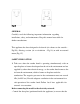
- Please make sure that the arrow is positioned on the same side as the appliance controls. Make 4, Ø8 holes in the ceiling and drive in 3 screws without completely tightening them(Fig2). Pay attention not to insert the screw into the hole marked with an X on the hole template (the screws and expansion plugs must be suitable for the type of wall). - Take the upper part of the structure B and insert the 3 slots onto the 3 screws that are not completely tightened. (Fig3) Rotate slightly to fit.
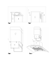
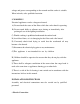
- If the cooker hood is supplied with a lower chimney piece that must be fixed to the hood body with screws, remove the anti-grease filters from the hood by releasing the filter latches (Fig.12). Then screw the lower chimney piece pipe to the inside of the hood, using screws P (Fig.13). Put the grease filters back in place. USE AND MAINTENANCE • It is recommended to operate the appliance prior to cooking.
of every four months. The saturation of the active carbon filter depends on the frequency of use of the appliance, by the type of cooking, and the regularity of cleaning the grease filters. (Fig.14) To remove the charcoal filters, remove the baffle filters, reach hand inside the unit to grasp one carbon filter at a time and rotate them toward the front of the appliance. The charcoal filters can now be removed. Always ensure to replace both filters at the same time.
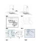
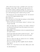
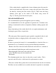
n FUNCTION KEYS: (Fig.18) A == OFF B == SPEED 1/―-‖Control C == SPEED 2/―+‖Control D == SPEED 4 E == LIGHT By pressing key B, C, or D, individually, the speed for each key will be the same as above table. At the same time, each corresponding button's light will flash. To stop the speed function press key A. If Speed 3 is required,press key C adjust ―+‖. At Speed 3, both key B and C indication light will flash on each button. To turn on the light press key E. To off the light press key E again.
the function key buttons. To stop the speed function press key B. If Speed 3 is required,press key D and adjust ―+‖. At Speed 3, both key C and key D indication lights will flash on each of the function key button. To turn on the light press key E. To turn off the light press key E again. n FUNCTION KEYS: (Fig.21, Fig.
will flash, push key A to switch to set hours and minutes, and then push C or E to set the correct time. The Clock’s system is 24 hours. When the motor is on, push the key B, the light is on, at the same time it shows " " is flashing as well on the digital display,and to push key B to switch hours and minutes. To set the time to automatically shut off the motor, push key C or E. Push key B for 3 seconds to stop the delay timer.
If the motor and light or only motor are on, pushing A turn on the automatic timer and it will count down 15 minutes before turning off the motor and light/ motor. Push B or D to adjust the time, and push A again to stop the timer. n FUNCTION KEYS: (Fig.24, Fig.26) A == Infrared Remote Control B == Timer (Automatic Shut Off) C == Digital Display(Timer/Speed) D == Speed F1/Cycle Control Adjustment/Off E == Light When key B is pressed, digital display screen will display 15 minutes.
Troubleshooting Problems Hood doesn’t work Poor airflow Possible reasons No electric supply Solutions Check the plug is connected Check the main switch is turned on Clean the filters and replace when dry Replace the charcoal filters Aluminum grease filters clogged Charcoal filters clogged Motor running but no Butterfly valve jammed Contact technician air flow High temperature The kitchen is not sufficiently Motor cuts off after safety device activated ventilated The hood is installed The hood must be lea
Correct Disposal of this product This marking indicates that this product should not be disposed with other household wastes throughout the EU. To prevent possible harm to the environment or human health from uncontrolled waste disposal, recycle it responsibly to promote the sustainable reuse of its materials. To return your used device, please use the return and collection systems or contact the retailer where the product was purchased. They can take this product for environmental safe recycling.