IMPORTANT SAFETY INSTRUCTIONS Carefully read the following Important information redarding installation safety and maintenance. Keep these instruction for future reference.
USERS OPERATING INSTRUCTIONS l INSTALLATION ADVICE IMPORTANT - PLEASE READ AND FOLLOW ü Before using this appliance please read these instructions carefully. ü Do not remove permanently affixed labels, warnings, or plates from the product. This may invalidate the warranty. ü Please observe all local and national codes and ordinances with regard to the installation of a gas hob. ü Please ensure that this product is properly grounded.
USER INSTRUCTION IMPORTANT PRECAUTIONS AND RECOMMENDATIONS l After having unpacked the appliance, check to ensure that it is not damaged. If you have any doubts, do not use it and consult your supplier or a qualified technician. l Packing materials (i.e. plastic bags, polystyrene foam, nails, packing straps, etc.) should not be left around within easy reach of children, as these may cause serious injuries. .
FEATURES L34in x W20in L23.5in x W20in L23.5in x W20in L31in x W17.7in L31in x W17.7in (L34in x W20in) Fig.1.1 Note: -The electric gas-lighting device is incorporated into the knobs. COOKING POINTS 1.Auxiliary(A) 2.Rapid(R) 3.Semi rapid(SR) 4.Triple flame(T) 5.Hotplate(H) CAUTION: If the burner flames are accidentally extinguished, turn the gas off at the control knob and wait at least 1 minute before attempting to relight.
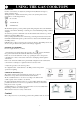
USING THE GAS COOKTOPS GAS BURNERS Gas flow to the burners are adjusted by turning the knobs(illustrated in (fig.2.1) which control the valves. Turning the knob so that the indicator line points to the symbols printed on the panel achieves to following functions: =closed valve =maximum rate =minimum rate The maximum aperture position permits rapid boiling of liquids whereas the minimum aperture position allows slimming or warming of food and maintaining boiling conditions of liquids.
CLEANING AND MAINTENANCE GENERAL RECOMANDATION Do not use steam jet cleaners because the humidity could enter into the appliance making it dangerous. ü Before you begin cleaning you must ensure that the hob is switched off. It is advisable to clean when the appliance is cold. ü All enamel surfaces have to be washed with soapy water or some other non-abrasive product with a sponge and are to be dried preferably with a soft cloth. ü Avoid leaving alkaline or acid substances (lemon juice, vinegar etc.
NOTE: This is extremely important! Please check before planning for service. CORRECT REPLACEMENT OF THE BURNERS It is very important to check that the burner flame spreader "F" and the cap "C" have been correctly positioned (see figs. 3.1 and 3.2). Failure to do so can cause serious problems. In appliances with electric ignition check that the electrode "S" (fig. 3.1) is always clean to ensure trouble-free sparking. The ignition plug must be very carefully cleaned.
INSTALLATION INSTRUCTIONS WARNING! THIS APPLIANCE HAS TO BE INSTALLED BY A QUALIFIED INSTALLER. Improper installation, adjustments, alterations, service or maintenance can cause injury or property damage. Consult a qualified installer, service agent, or the gas supplier.
The installer must refer to local/national codes GENERAL INFORMATION 1. Installation must conform with local codes or in the absence of local codes, with the National Fuel Gas Code, ANSI Z223.1 -Latest Edition. 12.Gas Manifold Pressure Natural gas - 5" W.C.P. LP/Propane - 10" W.C.P. 2.
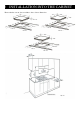
! INSTALLATION INTO THE CABINET Please take the cut-out size according to the cooktops dimension. 17.7” 34” 20” 31” 2.83” min 1.8” 29” 33” 18.9” 16.1” 21.3” min 2” min 2” min 1.6” min 1.6” 23.6” 20” 2.83” 22” 18.9” min 2” min 1.6” min 21.3” 21.
PROXIMITY TO SIDE CABINETS Important: Base cabinet construction must allow for size of cooktops cut-out. 1. Gas line opening: Wall-anywhere 11” 51/64(300mm) below underside of countertop; Cabinet floor – anywhere 3”1/8(79.2mm) from the rear wall. Grounded outlet: the electric cord with 3-prong ground plug has a length of 48”(122mm).Grounded outlet should be located within 36”(914.4mm) of right rear corner of cut-out. 2.
⑤ GAS CONNECTIONS All gas connections must be made according to national and local codes. This gas supply (service) line must be the same size or greater than the inlet line of the appliance. Sealant on all pipe joints must be resistant to the action of LP/Propane gas. The model/serial rating plate, located on the underside of the burner box, has information on the type of gas that can be used. If this information does not agree the type of gas available, check with the local gas supplier.
GAS CONNECTION SPECIFICATION 13
b) Any conversion required must be performed a qualified licensed gas service company. Please provide the service person with this manual before work is started on the cooktops. (Gas conversions are the responsibility of the dealer or end user.) c) This cooktops can be used with NATURAL or LP/PROPANE gas. It is shipped from the factory adjusted for use with LPG gas. d) Manifold pressure should be checked with a manometer. NATURAL gas requires 5,0"W.C.P. and LP/PROPANE requires 10,0" W.C.P. (see Figure 5.
CONVERSION TO LP/PROPANE GAS Every cooktops is provided with a set of injectors for the various types of gas. Select the injectors to be replaced according to the table below. The nozzle diameters, expressed in hundredths of a millimeter, are marked on the body of each injector. SETTING THE PRESSURE REGULATOR (Fig. 5.3) Attention: The regulator is pre-adjusted for both valves. Aside from the turning of the plug(1), there is no further customer adjustment necessary.
OPERATIONS TO BE PERFORMED WHEN SUBSTITUTING THE INJECTORS l l Remove the gratings, the burner covers and the knobs; Using a wrench substitute the nozzle injectors “J”(fig:5.4-5.5) With those most suitable for the kind of gas for which it is to Be used. The burner are conceived in such a way so as not to require the regulation of the primary air. REGULATING THE BURNER MINIMUM SETTING When switching from one type of gas to another.
⑥ ELECTRICAL CONNECTION If codes permit and a separate ground wire is used, it is recommended that a qualified electrician determine that the ground path is adequate. Check with a qualified electrician if you are not sure whether the cooktops is properly grounded. Do not ground to a gas pipe. The outlet must be checked by a qualified electrician to see if it is wired with the correct polarity. This appliance when installed. must be electrically grounded in accordance with local codes.
WIRING DIAGRAM IGNITION 18