
Instruction manual

20
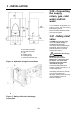
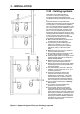
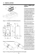
3.23.3 - 80/80 split
system
The heater is not supplied with fittings
for the flue gas discharge/air intake
connections. To connect the heater
to an 80/80 split system it is
necessary to order the special kit and
install it as shown in figure 11.
On the flue gas discharge side, it is
recommended to install stainless
steel pipes which are more resistant
to the formation of condensation.
Take particular care with the
installation of the pipe sections that
pass through the wall to the
outside; these must always allow
for normal maintenance actions,
therefore install the pipes inside a
liner to enable them to be pulled
out.
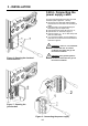
Make sure that vent pipe is pitched
down from the unit toward the
outside wall 1/4” (6 mm) per foot
(0.3 m). This will prevent any water
condensate from running back into
the heater.
Also make sure that air intake pipe
is pitched down from the unit
toward the outside wall 1/4” (6 mm)
per foot (0.3 m). This will prevent
any water rain go into the heater.
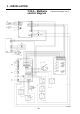
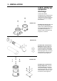
The heater is equipped with a
condensation collector which, if
used, must be connected to a
discharge pipe (see fig. 12 details G,
H, L, M). Details G, H, L, M are not
supplied with the heater.
The condensation collector is
designed to discharge the liquid
produced by a single heater.
If more than one heater is installed,
each one must be equipped with its
own condensation discharge pipe.
The flue gas discharge/air intake
system can be extended up to the
maximum distance indicated in
chapter 8 at the end of the manual.
Every 90° bend has an equivalent loss
to 3ft (1 m) of straight piping. Every
45° bend has an equivalent loss to
1.5ft (0.5 m) of straight piping.
If the air intake and flue gas discharge
terminals are positioned on the same
wall, they must be at a minimum
distance of 3ft (1 m) from each other.
The center line of the vent opening
must be at least 12” (305 mm) above
grade and at least 12” (305 mm) from
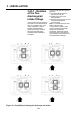
Figure 13 - Fixing of the flue gas discharge and air intake pipes
3 - INSTALLATION
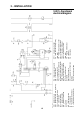
Figure 11 - Installation of the 80/80 split system
Figure 12 - Overall dimensions