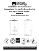
Installation and maintenance instructions for gas-fired condensing hot water boilers models: ONEX ASME certified INSTALLER, THESE INSTRUCTIONS TO BE AFFIXED ADJACENT TO THE BOILER. 62403466 R04 14/11/2008 (Book No. 62403466, Ed. Sep.
SAFETY INSTRUCTIONS WARNING: If the information in these instructions is not followed exactly, a fire or explosion may result causing property damage, personal injury or death. AVERTISSMENT: Assurez vous de bien suivre les instructions données dans cette notice pour réduire au minimum le risque d’incendie ou d’explosion ou pour éviter tout dommage matériel, toute blessure ou la mort - Do not store or use gasoline or other flammable vapors and liquids in the vicinity of this or any other appliance.
SAFETY INSTRUCTIONS 3
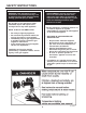
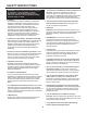
SAFETY INSTRUCTIONS In the event of a breakdown and/or malfunction of WARNING!!! These instructions must be read prior to installation. If the information in these instructions is not followed exactly, a fire or explosion may result, causing property damage, personal injury, or death. the boiler, turn off the unit and do not make any attempt to repair it. The boiler must be serviced exclusively by a qualified technician using original spare parts.
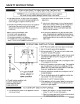
TABLE OF CONTENTS SAFETY INSTRUCTIONS ........................................................................................................................................................................ 2 TABLE OF CONTENTS ........................................................................................................................................................................... 5 1 - INSTALLATION - CODE REQUIREMENTS ..........................................................................
TABLE OF CONTENTS 11.1.3 - Filling the heating system ..................................................................................................................................... 39 11.1.4 - Filling of the domestic hot water heat exchanger (“45WN and 45WE” models only) .......................................... 39 11.1.5 – Auto-purging the heating system .......................................................................................................................... 39 11.
1 - INSTALLATION - CODE REQUIREMENTS 1.1 - National installation legislation - The installation must conform to the requirements of the authority having jurisdiction or, in the absence of such requirements, to the latest edition of the National Fuel Gas Code, ANSI Z223.1/NFPA 54 and or CAN/CSA B149.1, Natural Gas and Propane Installation Code.
2 - GENERAL INFORMATION 2.1 - Introduction Congratulations! You have effectively purchased one of the best boilers on the market. Each single part is built, tested and assembled, with pride, at the COSMOGAS factories, thereby guaranteeing optimum quality control. Thanks to on-going research carried out by COSMOGAS, this product has been conceived and is considered to be the best in its class with regards to respect for the environment. Great importance is also given to the end of the boiler’s useful life.
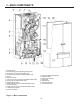
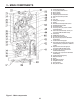
3 - MAIN COMPONENTS 1 - Automatic air vent 2 - Air intake and flue gas discharge fitting (venting system) 3 - U7 flue gas temp. sensor and flue safety switch 4 - Expansion tank (not present on 45AN and 45AE models) 5 - Air drum 6 - Air/gas mixer device 7 - U2 d.h.w. temp.
3 - MAIN COMPONENTS 22 - Combustion analysis tap 23 - U1 supply temperature sensor 24 - Burner window 25 - Air/gas manifold 26 - U6 high temperature limit sensor 27 - Flue gases back flow preventer 28 - Fan 29 - Gas valve 30 - Heating pressure gauge 31 - Display 32 - Domestic hot water temperature control 33 - Heating temperature control 34 - On/off power switch 35 - Three way valve (not present on 45AN and 45AE models) 36 - U3 domestic cold water temp.
4 - FUNCTION OVERVIEW Key to figure 2: 1 = boiler model 45WN or 45WE 2 = automatic air vent 3 = air intake 4 = flue gases discharge 5 = sealed combustion chamber 6 = expansion tank 7 = burner 8 = fan 9 = gas valve 10 = condensate discharge trap 11 = circulator pump 12 = 3-way valve 13 = secondary heat exchanger for d.h.w.
4 - FUNCTION OVERVIEW Key to figure 3: 1 = boiler model 45AN or 45AE 2 = automatic air vent 3 = air intake 4 = flue gases discharge 5 = sealed combustion chamber 7 = burner 8 = fan 9 = gas valve 10 = condensate discharge trap 14 = pressure gauge 17 = safety relief valve 20 = safety relief valve discharge 21 = condensation discharge pipe 22 = heating supply pipe 24 = gas inlet 26 = heating return pipe 45 = U7 = flue gas temperature sensor and high limit safety switch 46 = U1 = boiler temperature sensor 47 =
4 - FUNCTION OVERVIEW 4.1 - Intended use and functions of the boiler This gas-fired condensing boiler, is designed to be used for central heating and producing domestic hot water. The maximum output heat is always guaranteed for the production of domestic hot water since it is given priority over space heating demands. Follow the specific procedure in section 12.1 for the adjustment of the domestic hot water temperature. Depending on the model choosen, the following system types can be created: - 45WN.
4 - FUNCTION OVERVIEW 4.3 - A smart and intelligent boiler When connected to an outside sensor (optional), this boiler is designed to always work at the maximum efficiency. It will automatically change the supply temperature in relation with the outdoor temperature. The graph in figure 4 shows an example on how it can work. This graph represent an installation where the supply and return temperatures are 139°F and 115°F respectively , and the outside temperature is 23°F.
4 - FUNCTION OVERVIEW 4.4 - Characteristic curves of heating system’s residual head 45WN and 45WE boilers are fitted with its own specific circulator pump. The residual head at the boiler connections is shown in graph form in figure 5. Figure 5 - Residual Head for heating circuit for models “45WN” and “45WE” 4.5 - Boiler head loss curve 45AN and 45AE boilers are not fitted with an internal pump. The installer needs to install an external pump as illustrated in figure 17, item “6”.
5 - INSTALLATION - Mounting & gas and water connections 5.1 - Clearances for installation and servicing for models Figure 8 shows the clearances required for installation and servicing. NOTE: Service clearances are not mandatory, but are recommended to ensure ease of service should it be required. 5.
5 - INSTALLATION - Mounting & gas and water connections 5.4 - Choosing the installation location for 45WE and 45AE models CAUTION!!! The boiler must be installed on a vertical wall constructed to bear its weight or the boiler and building may be damaged. NOTE: The boiler must never be installed on carpeting. CAUTION!!! This boiler is designed also for direct outdoor installation.
5 - INSTALLATION - Mounting & gas and water connections 5.5 - Mounting the boiler Refer to figure 11: place the cardboard template, provided with the boiler, against the wall; ensure that the template is plumb and the screw holes line up with the wall studs; CAUTION!!! The wall bracket screws must be screwed into the buildings framing or other material capable of supporting the weight of the boiler or the boiler and building may be damaged.
5 - INSTALLATION - Mounting & gas and water connections 5.7 - Condensate disposal be connected to the domestic waste disposal system by means of an appropriate trap capable of preventing the pressurization of the condensate system and the return WARNING! The condensate trap of sewer gases (see figure 14); must be connected to the boiler per the following instructions or comply with national and/or local combustion gases will enter the codes for condensate neutralizer room.
5 - INSTALLATION - Mounting & gas and water connections 5.9 - Supply and return piping CAUTION!!! All heating system piping must be installed in accordance with the ANSI/ASME Boiler and Pressure Vessel Code, Section IV. All applicable local codes and ordinances must also be followed.
5 - INSTALLATION - Mounting & gas and water connections 5.13 - Gas supply piping Before installation a thorough The gas supply piping to the boiler must be properly sized to guarantee that the gas supply meets the maximum requirements. If more than one appliance is supplied by the same gas supply pipe, the gas supply piping must be sized based on the maximum possible demand. Do not neglect the pressure drop due to pipe fittings.
5 - INSTALLATION - Mounting & gas and water connections 5.15 - Suggested piping and wiring connections for the 45WN and 45WE versions Boiler Figure 16 shows the suggested piping and wiring connection for boiler models 45WN and 45WE. All component listed below, except the flue terminal needs to be field supplied.
5 - INSTALLATION - Mounting & gas and water connections 5.16 - Suggested piping and wiring connections for the 45AN and 45AE versions Boiler Figure 17 shows the suggested piping and wiring connections for boiler models 45AN and 45AE. All components listed below, except the flue terminal need to be field supplied.
6 - INSTALLATION - Electrical connections 6.1 - Electrical connections: overview WARNING!!! Label all wires prior to disconnection when servicing controls. Wiring errors can cause improper and dangerous operation! ATTENTION!!! Au moment de l’entretien des commandes, étiquetez tous les fils avant de les débrancher. Des erreurs de câblage peuvent entraîner un fonction-nement inadéquat et dangereux. S’assurer que l’appareil fonctionne adéquatement une fois l’entretirn terminé.
6 - INSTALLATION - Electrical connections 6.2 - Connecting the power supply cable To connect the electrical power supply cable, follow the steps below while referring to figure 18: remove the boiler casing following the instructions given in section 13.2 or 13.
6 - INSTALLATION - Electrical connections route the cable through an empty cable clamp in the junction box connect the cable leads to the “RT” terminals as shown in figure 18. NOTICE! the maximum room thermostat cable length permitted is 65 ft (20 m). For longer lengths, up to 300ft (100 m) a shielded cable, with the shield connected to the ground, must be used.
6 - INSTALLATION - Electrical connections 6.8 - Installing the remote command on 45WE and 45AE models Install the remote command (item “C” of figure 20) in a site inside the house.To connect the remote command to the boiler, proceed as follows: remove the boiler casing according to the instructions given in section 13.2 or 13.3 and open the junction box per section 6.2; use a two conductor cable with a minimum cross section of # 18 AWG. between the boiler and the remote command.
7 - INSTALLATION - Indirect storage tank connections 7.
7 - INSTALLATION - Indirect storage tank connections A = front cover of the electrical box B = plastic spring to open the electrical box C = Direction to open the electrical box D = Switches for the functional setting of the boiler Figure 22 - Contro board and junction box board details 29
8 - INSTALLATION - Vent & combustion air (c) Dans la mesure du possible, fermer toutes les portes et les fenêtres du bâtiment et toutes les portes entre l’espace où les appareils toujours raccordés du système d’évacuation sont installés et les autres espaces du bâtiment.
8 - INSTALLATION - Vent & combustion air 8.2 - Venting systems The vent system shall be installed so as to prevent the accumulation of condensate. When horizontal vent runs exceed 5 ft (1.5m), they must be supported at 3 ft (0.98 m), WARNING!!! The vent installation intervals with overhead hangers. must be in accordance with Part 7, Venting of Equipment, of the latest Horizontal vent systems shall edition of the National Fuel Gas terminate at least 4 ft (1.22 m) Code, ANSI Z223.
9 - INSTALLATION - Split 80/80PP venting system 9.1 - “Split 80/80PP” system (polypropylene) or AL29-4C (UL 1738/UL C 636) system NOTE:This vent system is not available for 45WE and 45AE models The boiler is not supplied with the fittings needed for separate vent and combustion air systems. A special kit must be ordered to connect the boiler to separate vent and combustion air systems. Figure 24 shows fitting “A” that can freely turn 360 degrees for optimum installation versatility.
9 - INSTALLATION - Split 80/80PP venting system Horizontal vent systems should be as short and straight as possible. The vent system must be both gas tight and watertight. All seams and joints must be joined and sealed in accordance with the vent system manufacturer’s instructions. WARNING!!! Carefully follow the installation steps below for the assembling the split pipe venting system (elbows and extensions), as illustrated in figure 26.
9 - INSTALLATION - Split 80/80PP venting system 9.2 - “Split 80/80PP” system components Some of the most commonly used components for installing the “Split 80/80PP” polypropylene vent and combustion air systems are listed below: 62617286 - No. 1 - Split adaptor 80/80 PP 61302011 - No. 29 - Flue exhaust roof terminal 62617236 - No. 11 - 3ft PP M/F extension 62617240 - No. 14 - 60 ft PP flexible extension 62617241 - No. 16 - Spacer for PP flexible extension 62617244 - No.
9 - INSTALLATION - Split 80/80PP venting system 9.3 - “Split 80/ 80PP” system: installation examples Three installation examples can be seen in figure 29: the first example shows the vent system directly penetrating the roof with the collection of condensation inside the boiler itself. The combustion air system must be pitched outward 1/4 in/ft (21 mm/m) to prevent rainwater from entering the boiler.
10 - INSTALLATION - Coaxial 60/100PP venting system 10.1 - “Coaxial 60/ 100PP” polypropylene system The boiler is not supplied with the fittings needed for connecting a coaxial vent/combustion air system. A special kit must be ordered to connect the boiler with the “Coaxial 60/100PP” polypropylene vent.
10 - INSTALLATION - Coaxial 60/100PP venting system 10.2 - “Coaxial 60/100 PP” system components The following coaxial polypropylene vent and combustion air system components are available, on request, for installing the “Coaxial 60/100PP” system 62617255 - No. 2 flashing for roofs pitched between 15° and 25° 62617234 - No. 1 - In line 90° PP coaxial M/F elbow 62617252 - No. 6 - In line 45° PP coaxial M/F elbow 62617231 - No. 7 - 3ft (1m) PP coaxial extension 62617250 - No.
10 - INSTALLATION - Coaxial 60/100PP venting system 10.3 - “Coaxial 60/ 100PP” system: installation examples When a coaxial vent and combustion air system is installed, figure 32, whether vertical or horizontal, it must be sloped 1/4 in/ft, (21 mm/m) towards the boiler. CAUTION!!! Maintain the distances given in figure 33, between the vent terminal and the wall and also between the vent terminal and the ground level (snow line) Figure 32 - Installation examples for the coaxial pipe (see section 10.
11 - OPERATING 11.1 - Operating Before starting the boiler, the following must be done. 11.1.1 - User instructions The user must be correctly instructed by the installer, on how to operate the boiler, in particular: Make sure that the user keeps this manual and all other documentation included with the boiler.
11 - OPERATING 11.2 - General warnings concerning gas supply When starting up the boiler for the first time the following must be checked: That the boiler is supplied with the type of fuel that it is configured to use. Read sections 11.3 and 11.4 That the gas supply pressure is within the maximum and minimum values given in listed on the boiler rating plate. The gas supply pressure must be checked with boiler on and the boiler off.
11 - OPERATING 11.7 - Gas supply pressure checking and adjustment The gas supply pressure must match that listed on the boiler rating label. Check the gas supply pressure by following the steps below: close the manual gas shut off valve, figure 16 and 17, item “3”; follow the steps in section 13.2 or 13.3 to remove the front cover; turn the screw in pressure connection “D” shown in figure 35 three turns counterclockwise; connect a manometer with graduations of at least 0.1 in.W.C. (0.
11 - OPERATING 11.8 - Check the combustion air pressure The boiler has a factory-set air/gas ratio. The pressure of the gas at the burner is indirectly controlled by the blower. The combustion air pressure is checked inside the boiler and must correspond with that shown in the table in section 14 under the item “combustion air pressure”. To carry out the check, proceed as follows while refering to figures 36 and 37: use a differential manometer with a precision of at least 0.1 in.W.C. (0.
11 - OPERATING 11.9 - Checking and adjusting CO2 levels Section 14 lists the correct CO2 ranges for a boiler running at normal operating conditions at an altitude below 3000 ft (1000m). CO2 values outside of the ranges given in section 14 may lead to malfunctioning of the boiler and cause it to prematurely fail.
11 - OPERATING 11.10 - Adjusting the heating capacity This boiler has been engineered with an “intelligent” micro-processor control that will adjust the heating output to match the system demand. To maximize the effectiveness of the found in system, the parameters the “Installers menu”, in section 12.11, can be adjusted set the maximum heating output to the effective maximum load necessary for the system. The parameter can be adjusted from 100 (factory set value), to 1.
12 - USE 12.1 - Adjusting the domestic hot water temperature The domestic hot water temperature is adjusted by turning knob “32” shown in figure 1. When the knob is turned, the display, item “31” in figure 1, shows a and the temperature being flashing selected. The range within which the domestic hot water can be set is 104°F (40°C) to 140°F (60°C) or from 113°F (45°C) to 158°F (70°C) when an indirect storage tank is used. For boiler model 45WE and 45AE, operate on knob “C” of figure 43. 12.
12 - USE proceed to make the appropriate adjustments bearing in mind that: A - each parameter must be set in small degrees; B - after each parameter change, wait at least 24 hours in order to see the result; C - the closer the adjustment curve matches the actual load of the building, the greater the comfort and the energy savings will be; D - knob “33” in figure 1 can be used to make the small line shifts, “b”, shown in figures 40 and 41.
Calculated temperature (°C) Calculated temperature (°F) 12 - USE OA = Inclination of the line Ob = Minimum heating temperature Oc = Maximum heating temperature br = “Fix point” of the angle fulcrum of the line b = parallel shift of the line (adjusted by the heating knob, item “33” of figure 1) Outside temperature (°C) Calculated temperature (°C) Calculated temperature (°F) Outside temperature (°F) Outside temperature (°C) Outside temperature (°F) Calculated temperature (°C) Calculated temperature
12 - USE 12.5 - Boiler switch settings The control board shown in figure 1, item “14”, and figure 22, contains a series of switches that allow the boiler to be configured to match the application. The table below lists each switch and its corresponding funtions. SWITCH 1 2 3 4 5 6 7 8 Position OFF ON OFF ON OFF ON OFF ON OFF ON OFF ON OFF ON OFF ON CAUTION!!! Improper setting of these switches could cause the boiler to malfunction resulting in improper system performance.
12 - USE 12.10 - “Users’ menu” or keys, to use the change the value of the selected parameter. NOTE: If no key is pressed for more than 60 seconds, the control automatically exists the “Users’ menu”. Any parameter change not When entering the “Users’ menu”, the display, item “31” in figure 1, will start blinking indicating that a change of mode has taken place.
12 - USE 12.11 - “Installers’ menu” CAUTION!!! Changing these parameters could cause the boiler and therefore the system to malfunction. For this reason, only a qualified technician who has indepth knowledge of the boiler should change them. The boiler’s micro-processor makes this menu of parameters available to the qualified technician for the analysis of the functioning and adjustment of the appliance to the system.
12 - USE The table below lists each “Installers’ menu” parameter, what it affects and its adjustment range.
12 - USE 12.12 Diagnostics During the normal operation of the boiler, the display item PARAMETER “31” in figure 1, continually shows the operating status of the boiler as shown below (see also section 16): INFORMATION ON DISPLAY ITEM “2” OF FIGURE 42 DESCRIPTION Boiler in stand-by mode or pause (no request for heating or domestic hot water) Boiler temperature (°F) Anti-freeze function active Boiler temperature (°F) Boiler not in lock-out mode but in warning.
12 - USE 12.12.1 - Diagnostics: “L” lock-outs Lock-out “L” Code description Checks to make Solutions L01 No flame detected after three ignition attempts. Check: a-correct gas supply pressure (see section 11.7); b-ignition spark (see section 13.5); c-correct combustion air pressure (see section 11.8); d-120Vac at the gas valve; e-resistance of the two gas valve coils should be 0.18 kohm and 1.
12 - USE 12.12.1 - Diagnostics: “L” lock-outs (continued) “L” Code Lock-out description Solutions Controls L18 Program error Replace the power control board L19 Flame sensed for 10 seconds, after the closure of the gas valve Replace the gas valve, or replace the power control board L20 Flame sensed before opening of the gas valve.
12 - USE 12.12.2 - Diagnostics: “E” blocking errors “E” Code E01 Blocking description Checks to make Solutions U1 boiler temperature Check that the electrical resistance of sensor circuit interrupted. the sensor corresponds with the graph in section 13.
12 - USE 12.12.2 - Diagnostics: “E” blocking errors (continued) “E” Code Blocking description Checks to make Check that the electrical resistance of the sensor corresponds with the graph in section 13.14; check that the electrical connection cables between the sensor and the power control board Check that the electrical resistance of the sensor corresponds with the graph in section 13.
12 - USE 12.13 - Remote command for model 45WE and 45AE Because the 45WE and 45AE boilers are intended also for outdoor installation, they are supplied with a remote commad that can help you to drive the boiler from inside building. Heating and domestic temperature regulation and reset of the boiler, may be performed directly on the remote command of figure 43. On remote command are present two lights: - Green light continuously ON: central heating is correctly running; - Green light blinking every 7 sec.
13 - MAINTENANCE 13.1 - General precaution WARNING!!! Never store combustible materials, gasoline or any product containing flammable vapors and liquids in the vicinity of the boiler. Failure to comply with this warning can result in extensive property damage, severe personal injury or death! WARNING!!! Never obstruct the flow of combustion and ventilation air.
13 - MAINTENANCE 13.2 - Removing the casing for models 45WN and 45AN In order to remove the casing, follow the steps below while refering to figure 44: remove screws “A”; raise latch “C”; remove the front cover; press the two plastic springs, item “L”, down; lower the electrical box; lift latch “G”; pull the bottom of cover “H” out by around 4 in (10 cm); lift cover “H” up by around 1in (2 cm) and remove it.
13.3 - Removing the plastic cover on a 45WE and 45AE boilers In order to remove the casing, follow the steps below while refering to figure 45: remove screw “E”; push upward, with your hands, in the points indicated by “Q” and “R”; pull-out all the cover press the two plastic springs, item “L”, down; lower the electrical box “S”; lift latch “G”; pull the bottom of cover “H” out by around 4 in (10 cm); lift cover “H” up by around 1in (2 cm) and remove it.
13 - MAINTENANCE protect the gas valve outlet, from entering any object or condensing water; remove the entire fan - burner assembly, detail “A” in figure 46; use a cylindrical brush with plastic bristles to clean the inside of the combustion chamber, detail “H” in The burner and primary heat exchanger figure 46; must be cleaned every year.
13 - MAINTENANCE 13.5 - Correct positioning of the ignition and flame detection electrodes For the boiler to work properly the electrodes must be positioned as shown in figure 47: the distance between the ignition electrodes “A” and “B”, must be between 0.08 in (2 mm), and 0.082 in (2.5 mm); the distance of the ignition electrodes to the burner surface must be between 0.196 in (5.0 mm), and 0.215 in (5.5 mm); the distance of the flame detection electrode to the burner surface must be between 0.236 in (6.
13 - MAINTENANCE 13.7 - Condensate trap cleaning The condensate trap must be cleaned every year. Follow the steps below to properly clean the condensate trap and its associated components while refering to figure 48: run the fan as described in section 13.13.2, to minimize the amount of liquid present in the trap, item “A”; follow the steps in section 13.2 or 13.
13 - MAINTENANCE 13.8 - Circulator pump motor replacement (only for 45WN and 45WE models) Figure 49 - Replacing the pump motor (only for 45WN and 45WE models) To replace the circulator pump follow the steps below while, refering to figure 49: follow the steps in section 13.11 to isolate and drain the water from the boiler; follow the steps in section 13.
13 - MAINTENANCE 13.10 - 3-way valve removal (only for 45WN and 45WE models) The 3-way valve, detail “F” in figure 51, directs hot water produced by the primary heat exchanger to the heating circuit or to the secondary heat exchanger for the production of d.h.w. To replace it follow the steps below while referring to figures 50, 51 and 52: follow the steps in section 13.11 to isolate and drain the water from the boiler; follow the steps in section 13.2 or 13.
13 - MAINTENANCE 13.11 - Draining the heating side of the boiler To drain the heating side of the boiler follow the steps below: allow the water inside to cool by switching off the room thermostat and turning knob “33” in figure 1 to minimum.
13 - MAINTENANCE 13.14 - Water and flue temperature sensor The boiler has a number of sensors that measure temperature. The electrical resistance between the sensor wires must correspond with the values shown in figure 53. The temperature sensors are: U1; U2, U3, U5, U6, U7 and U8. The location of each sensor can be found in figures 1 and section 13.16 and 13.17. Figure 53 - Water temperature sensors’ curve 13.
13 - MAINTENANCE 13.16 - Functional wiring diagram WARNING!!! Label all wires prior to disconnection when servicing controls. Wiring errors can cause improper and dangerous operation! Verify proper operation after servicing Failure to comply with this warning can cause extensive property damage, severe personal injury or death! ATTENTION!!! Au moment de l’entretien des commandes, étiquetez tous les fils avant de les débrancher.
13 - MAINTENANCE LEGEND TO FUNCTIONAL AND MULTIWIRE DIAGRAM ALA - Alarm output CM - Power control board CR - Remote command (only for 45WE and 45AE models) EA - Ignition electrode ER - Flame detection electrode EPO - External pump (REQUIRED FOR MODEL 45AN) EV3V - External three way valve (optional) F1 - Fuse 2Amps FPR - Flue pressure switch GS - Spark generator IG - Main electrical switch J1 - Six poles connector J2 - Four poles connector J3 - Twelve poles connector J4 - Four poles connector J5 - Sixteen po
14 - TECHNICAL DATA MODEL Country of destination Type of boiler Category of discharge chimney CSA certificate N° Maximum Heat input Minimum heat input Efficiency at maximum heat input (160°F/140°F) Maximum Heat output (160°F/140°F) Efficiency at minimum heat input (122°F/86°F) Minimum heat output (122°F/86°F) Gas flow rate Natural gas LP Gas Gas supply pressure Natural gas LP Gas Minimum gas supply pressure Natural gas LP Gas Maximum gas supply pressure Natural gas LP Gas Combustion air pressure with min.
15 - SPARE PARTS 12345678910 11 12 13 14 15 16 17 18 - 60504206 60510022 62111016 62622011 60802018 60702030 62649004 60702047 62111017 60803027 61405025 60801116 60803011 60702055 62630136 60806020 60322012 60701001 CABLE UL IGNITOR CONN 90° L155 SPARK GENERATOR NO CABLE UL SENSOR NTC 10 KOHM A KLIP DIAM.22 COPPER PIPE D22 M/F 3/4"G-1"G 3/4" RING NUT O-RING NBR 2,62 X 20,63 PRIMARY HEAT EXCHANGER C.R.R ASME GASKET EPDM X OSSIDO D84 H7 SENSOR NTC 10 KOHM 1/8" GASKET COPPER 1/8" SP.
15 - SPARE PARTS 37 38 39 - 62629036 61504029 60909008 40 41 42 43 44 45 46 47 48 49 50 51 52 53 54 55 56 57 58 59 60 61 62 63 60703032 61404108 60703030 62651016 60801136 61404114 60702049 60702048 60408261 60702056 61901029 61405174 60702051 61404109 60801080 60701013 60815011 60404253 60801081 60505022 60505023 60505024 60406069 60702050 - BURNER HEAD EXTRUSION L.25MM THERM. INSULATION VERMICULITE D117 F74 SP21,5 GASKET. SIL. D157 F145 H6,7 BASE MANIFOLD AIR ALUMINUM GASKET SIL.
15 - SPARE PARTS Bottom of the boiler for 45WN and 45WE models 90 91 92 93 94 95 96 97 98 99 100 101 102 - 61202024 60808002 61202027 61408005 62113035 60704003 60801134 61205010 60113004 60101082 61202025 61202028 60107005 PLUG PISTON BODY OT. SPRING FORCK 3V UPPER PISTON HYDRONIC SUPPLY GROUP.
15 - SPARE PARTS Bottom of the boiler for 45AN and 45AE models 114 115 116 117 118 119 120 122 123 124 125 126 127 128 129 130 131 132 133 134 135 - 60305073 60702054 60901022 60901023 60110025 60701004 61101001 60101225 60802018 60801135 62623248 61408008 60101193 60107014 60107015 61408009 60101124 62113041 60101064 60110001 60815012 BY-PASS PIPE O-RING 4075 EPDM 3,53 X 18,64 FRONT THERM. INSULATION “ACQUAJET” REAR THERM.
15 - SPARE PARTS External jacket for 45AE and 45WE models 136 137 - 62606030 60703039 PLASTIC EXTERNAL JACKET GASKET EPDM INTERNAL D60 75
Domestic hot water Boiler in stand-by Visualization in normal operating condition (see section 12.12 ) User’s menu, with thermostatic CH settings to 00 (see section 12.10) User’s menu, with climatic CH settings to 01 or 02 (see section 12.10) Installer’s menu (see section 12.11) Overrides menu (see section 13.13) Last lock out error Last blocking error D.H.W. temp. setting Central heating temp.
Anti legionellae protection D.H.W. active more than 120 min. Blocking error Lock-out Anti Freeze protection Central heating Last lock out error Last blocking error Fan speed rpm/100 Room therm. state 77 Disabled parameter Energy saver display State of the knobs Heat. temp. reduction by open RT Angle fulcrum Reaction to outdoor temp.
16 - MENU’S FLOW CHART parameters could cause the boiler and therefore the system to malfunction. For this reason, only a qualified technician who has indepth knowledge of the boiler should change them. To enter this menu you must: shut Off the main electrical supply; move the switch n° 7 (see figure 22, item “D”) to the ON position; lite On the main electrical supply. Now ty is displayed. Use plus and minus keys to change the value; use RESET key to save the value and swap to the next parameter.
NOTE 79
COSMOGAS srl Via L. da Vinci 16 47014 - Meldola (FC) ITALY www.cosmogas.com info@cosmogas.com Spare parts are available from your local authorized wholesale distributor. For a location of the one nearest you call 413-564-9538.