Communication protocol User's Manual
Table of Contents ■ I2C Bus Interface Option 1. Introduction. ......................................................................................................................... 1 1-1 Serial clock (SCL & SDA)................................................................................................. 1 1-2 Addressing. ...................................................................................................................... 1 2. I2C Bus Protocol .........................................
8. Commands. ........................................................................................................................... 10 8-1 Command set. .................................................................................................................. 10 8-2 Command descriptions. ................................................................................................... 10 8-2-1 Data Transmission. ...................................................................................
I2C Bus Interface Option 1. Introduction 1) Manufacturing related data (Include model name, MFG date etc...) 2) Actual output voltage, output current and internal temperature of the SMPS. 3) Statuses of the SMPS. 4) ON / OFF control and Output voltage / current setting. 1-1 Serial clock (SCL & SDA) The I2C interface is designed to run with a serial clock speed of 100KHz. Both SCL & SDA signals is an open drain output that may be wired-ORed with the other SMPS.
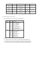
3. Operation and Functions Address Byte Function Type 0x00-0x0F 16 Manufacture Read 0x10-0x1F 16 Model name Read 0x20-0x23 4 (Not used) 0x24-0x27 4 Revision Read 0x28-0x2F 8 Date of manufacture Read 0x30-0x3F 16 Serial Number Read 0x40-0x4F 16 Country of MFG. Read 0x50-0x51 2 Rated Output Voltage Read 0x52-0x53 2 Rated Output Current Read 0x54-0x55 2 Max. Output Voltage Read 0x56-0x57 2 Max.
0x74-0x79 6 (Not used) 0x7A 1 ** Reserve ** 0x7B 1 ** Reserve ** 0x7C 1 Control 0x7D-0x7F 3 ** Reserve ** R/W 3-1 Status Register (0x6C, 0x6F) : Fault is indicated by "1" and Good level is indicated by "0".
3-2 Control Register (0x7C) : Adds Bit Function Meaning 0x7C Bit0 Bit1 Bit2 Bit3 Bit4 Bit5 Bit6 Bit7 Power control (Not used) Command update Command error (Not used) (Not used) ** Reserve ** Remote control 0:PWR-OFF, 1:PWR-ON 0:Complete, 1:Required 0:Valid, 1:Error 0:Control by VCI,ACI, ENB 1:Control by Software (I2C or RS232/485)
4. Measurements and Calculation Example To simplify the explanations of I2C, user may enter values of address commands index [adds] and the bit value of address commands index [adds.bit] as follow: Ex: [0x6C] indicates the value on the address “0x6C” [0x7C.7] indicates the value of bit 7 on the address“0x7C” 4-1 Output voltage read back To read the values of the addresses of [0x61] and [0x60];[0x61] as High byte and [0x60] as Low byte.
1 = Internal temperature is over 75°C.
bit 4 SMPS Fail. 0 = SMPS works normal. 1 = Unit fail, Power shutdown. bit 3 Fan Fail. 0 = Fan works normal 1 = Fan fail, Power shutdown. bit 2 OTP Shutdown. 0 = Normal Internal temperature. 1 = Internal temperature is over 85 O C, Power shutdown. bit 1 OLP Shutdown. 0 = Normal 1 = Overload shutdown. bit 0 OVP Shutdown. 0 = Normal. 1 = Overvoltage shutdown.
After voltage setting, the voltage stores in the buffer of SMPS. To renew the O/P Voltage, please refer to the explanations of 5-3.
5-2 Output current setting To multiply the setting current of 100 and convert the value into hex code, please write High byte first followed by Low byte on the addresses of 0x73, 0x72. Ex: To set O/P current setting to 45.75A, please multiply 45.75 by 100, then convert 4575 into Hex code. Write hex code of 0x11DF, 0x11, 0xDF into the address of 0x73, 0x72. After current setting, the current stores in the buffer of SMPS. Please refer to the explanations of 5-3, to renew the O/P current.
RS-232 / RS-485 Communication protocol 6. Introduction 1) ON / OFF control and ON / OFF Status Query. 2) Output voltage / current setting and Query. 3) Actual output voltage, output current and internal temperature Query. 4) Status Query. 5) Manufacturing related data Query (Include model name, MFG country etc ...). 6-1 Communication Protocol Protocol invariably uses 4800,N,8,1. (The setting is not changed.
7. UART protocol of unit 7-1 Data Transmission The UART transmit and reply command are both executed by ASCII codes, and use CR (ASCII code 0x0D) & LF (ASCII code 0x0A) for termination. 7-2 SMPS Addressing 1. In single unit operation, setting address is unnecessary. 2. To control multiple SMPS via RS-485 (Host PC), please do the following: 1) Please set Addr.
8.
8-2-1 Data Transmission Syntax: ADDS Parameter: 0 <= adds <= 7 Description: When device receives a command, even if the addressing flag is set to 1 or clear to 0, UART will execute this command. Only if the addressing of device is the same with , UART will set the device addressing flag to 1 and reply “ = > CR LF” to express that the execution is completed. If address of the device isn't the same with , UART will set the device addressing flag to 0, but will not reply.
8-2-5 Power ON / OFF / Query Syntax: POWER Parameter: 0 <= type <= 2 Description: = 0: To Power off SMPS. Control mode will change to REMOTE = 1: To Power on SMPS. Control mode will change to REMOTE = 2: Query the status of power ON/OFF, Echo : 0 -> Remote Disable, Power Off. 1 -> Remote Disable, Power On. 2 -> Remote Enable, Power Off. 3 -> Remote Enable, Power On. 8-2-6 Output Voltage Setting Syntax: SV Parameter: value -> Voltage value for setting.
8-2-11 Output Current Query Syntax: RI? Parameter: None. Description: To query the output current value 8-2-12 Internal Temperature query Syntax: RT? Parameter: None. Description: Query the internal temperature value of SMPS. SMPS will transmit the internal temperature value. The internal temperature info is provided in °C.
e. g. 1: The reply of STUS 0 is “04” -> Express Hex code : 0x04 has transformed to binary code. 0000 0100 B0 = 0 B1 = 0 B2 = 1 → OTP Shutdown. B3 = 0 B4 = 0 B5 = 0 B6 = 0 B7 = 0 24 : the power supply will soon be over temp. protected 34 : the power supply is in the over temp. protection mode (OTP) e. g. 2: The reply of STUS 1 is “02” -> Express Hex code : 0x02 has transformed to Bin code. 0000 0010 B0 = 0 B1 = 1 → Power CMD Active Software Command.
8-2-15 SMPS Information Query Syntax: INFO Parameter: type = 0 to 6 Description: Query device information, device will transmit the related information. = 0 -> Manufacture. = 1 -> Model Name. = 2 -> Output Voltage. = 3 -> Revision. = 4 -> Date of MFG. = 5 -> Serial Number = 6 -> Country of MFG. 8-2-16 Query rated voltage and rated current Syntax: RATE? Parameter: None. Description: Query rated voltage and current of SMPS.
Attention When use RS232 / 485 to control AE/AEK series SMPS, user must follow the rules as stated below. A: Before entering the power-on command (POWER 1, GLOB 1), it is recommended to set / check the voltage and current value in advance before power on. After receiving the response from SMPS, user may then assign power-on command. B: All characters of RS232/485 must be transmitted completely between 400ms according CR LF (0D0A).