
AE & AEK Series Communication Protocol


I
2
C Bus Interface Option
1.
Introduction
1)
Manufacturing related data (Include model name, MFG date etc...)
2)
Actual output voltage, output current and internal temperature of the SMPS.
3)
Statuses of the SMPS.
4)
ON / OFF control and Output voltage / current setting.
1-1
Serial clock (SCL & SDA)
The I
2
C interface is designed to run with a serial clock speed of 100KHz.
Both SCL & SDA signals is an open drain output that may be wired-ORed with the other SMPS.
This bi-directional signal is used to strobe the clock (SCL) / data (SDA) of SMPS input and output.
SCL & SDA signal should be connected to +5V via a pull-up resistor of 2K Ohm.
1-2
Addressing
To set the address of SMPS, please adjust the Addr.Switch on the SMPS panel. User
can adjust the address switch up to max. of 8 SMPS.
2.
I
2
C Bus Protocol Of SMPS
The I
2
C bus option of SMPS are provided with I
2
C type EEPROM device protocol
(24C02).
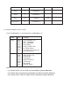
2-1
Device slave address (7 bit device address):
Device type identifier (Fixed)
Unit Enable
(variable address)
R/W
b7
b6
b5
b4
b3
b2
b1
b0
1
0
1
0
E2
E1
E0
R/W
2-2
Write mode sequences:
S
1 0 1 0 E2-E0 0
A
A7-A0
A
D7-D0
A
P
2-3
Read mode sequences:
S
1 0 1 0 E2-E0 0
A
A7-A0
A
S
1 0 1 0 E2-E0 1
A
D7-D0
A
P