CR-10 Remote Control User’s Manual www.cotek.com.
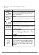
Remote control introduction Press the ON / OFF button on the front. The SD-series starts working normally. After switching on expect a five to ten second delay. The SD-series will be operating in normal condition when either of the following messages are displayed on the LCD panel screen : 5.5 30.5 2-φ3.3 46 LED Indications : ˙GRID: Displays incoming AC input status. AC Input AC input ON AC input OFF LED Status Green OFF ˙Inverter: Displays the SD-series working statuses.
LCD Remote Control Panel Selection Buttons : ˙Function : Function [Up] You can use the “up” button to scroll through the menus or to select the value for set up under setting mode. [Down] You can use the “Down” button to scroll through the menus or to select the value for set up under setting mode. [Page Up] You can use the “Page Up” button to scroll through the menus. [Page Down] You can use the “Page Down” button to scroll through the menus.
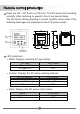
LCD Rear View Introduction Jump (reference 1 ) The “J1 jump” is placed inside the remote controller. ˙J1 jump “open” J1 Jump Open “CTL” Input Voltage 5 ~ 60 VDC 0V SD-series Turn ON Turn OFF “CTL” Input Voltage 5 ~ 60 VDC 0V SD-series Turn OFF Turn OFF ˙J1 jump “short” J1 Jump Short Note: The “J1” jump default mode is “short”.
˙ALM (PIN1) When the SD-series has the warning or the protection displayed, simultaneously this “ALM” pin will changing output to 5 Volt / 10mA control signal to provide the user. ˙ENB (PIN3) User can USE this “-ENB” pin to control the SD-series to turn ON or turn OFF. WARNING! To turn “ON” the SD-series by operating the –ENB function of LCD Panel, the SD-series inverter cannot be turned OFF by any other operations, only by the MAIN “OFF” SWITCH. ˙ -Vcc (PIN4) This is LCD remote control panel ground.
Display tree: Power Switch ON INVERTER Initialization.. Vi=xx.xxVo=xxx.x FQ=xx.x Io=xx.
Vi:XX.X FQ:XX.X Vo:XXX.X Io:XX.X FQ = xx.x →Display the INV frequency. Io = xx.x →Display the INV output current. FQ = xx.x →Display the INV frequency. Io = xx.x →Display the INV output current. Parameter Setting: Press button before entering the “User Interface” menus. ˙User Interface 1. LCD contrast : Sets the LCD screen contrast. Default = 50% Setting range = 0% ~ 100% Setting Menu LCD Contrast SETT 0 ~ 100 2. LCD Auto-off : Sets the LCD screen backlight auto off timer.
Setting Menu Buzzer Setting SETT(RS-232) 0 1 2 3 4 5 6 7 Buzzer(Beep sound) Disable SHDN Alert Alert , SHDN MSG MSG , SHDN MSG , Alert MSG , Alert , SHDN 5. Alert Setting : When alert occurs, the internal dry contact relay will open/close. Default = Alert, SHDN Setting range = 0~3 Setting Menu RS-232 Baud rate SETT (RS-232) 0 1 2 3 Alert (LCD) Disable SHDN Alert Alert , SHDN 6.
˙I/P Parameter 1. OVP Setting : Set the Over Voltage Protection (OVP) and shutdown. Default = 16 VDC @ 12V Model, 32 VDC @ 24V Model. 64 VDC @ 48V Model Model 12V 24V 48V Setting value range 15 VDC ~ 16 VDC 30 VDC ~ 32 VDC 60 VDC ~ 64 VDC 2. OVP Recovery : When the DC input voltage is higher than the OVP setting, the SD-series shuts-down; once the input voltage falls below the set OVP value, the SD-series will automatically restart. Default = 15 VDC @ 12V Model, 30 VDC @ 24V Model.
5. UV Alarm : Setting Under Voltage (UV) alarm. When the input voltage is lower than the set value, the SD-series will sound a “beep” to remind you that the unit is going to shut-down. In the meantime, the contact in the internal Dry Contact Relay will open / close. Default= 10.5 VDC @ 12 V Model, 21 VDC @ 24 V Model. 42 VDC @ 48 V Model Model 12V 24V 48V Setting value range 10.5 VDC ~ 11.
Example1: AC input = 230 VAC / 50Hz, User setting Value= 7Hz When the SD-series “Output frequency” is within The Range of 43 Hz~57 Hz, the internal transfer relay will close. When the output frequency is less than 43 Hz or more than 57 Hz, the internal transfer relay will still open. Example2: When user setting value= Disable, the SD-series “Output frequency” is within the range of 47 Hz~63 Hz, the internal transfer relay will close. Default= 7Hz 4. Overload Alarm : Set the overload alarm.
7. Bypass Relay : The setup is provided in one of the following two ways. On-line Mode or Off-line Mode ( Exacting, Normal, Haphazard). Default= Normal (Off line). Model SETT Setting value range Haphazard 0 The transfer relay will switch “ON” or “OFF”. Conformance to, phase and frequency synchronization will not be considered. Normal 1 The transfer relay will be “ON” if AC input (Grid) power is available.