CR Series User’s Manual CR-20 Remote Control
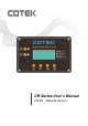
1.0 Overview CR-20 is a remote control designed for connecting to SL inverter/charger. The package is including: (1) CR-20 (2) 1.5m Cable (3) User Manual Fig. 1 Fig. 1 (Unit: mm) The CR-20 is equipped with the following features : 1.1 LED Indicators The LEDs provide the inverter/charger statuses in a straightforward way. 1.
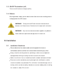
1.3 ON/OFF Pushbuttons (x2) To turn on/off inverter or charger quickly. 1.4 Buttons Pressing buttons allows you to select a menu item or to save a setting, once it is displayed on the LCD screen. WARNING: Turning the unit OFF does not mean to disconnect the batteries or AC Power Source. Therefore the “AC output load” is still active. WARNING: Only use the remote control cable supplied, using different cables could cause permanent damage to the SL inverter unit 2.0 Installation 2.
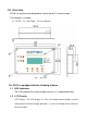
2.2 Installation Overview The remote is required in order to connect the inverter/charger. Each inverter/charger must be connected directly to the remote using the supplied RJ11 communication cables. The remote must be located close to the inverter/chargers within 25 meters and acts as the system control panel. 2.3 Mounting the Inverter Select an appropriate location to install the remote. Mount the remote base to the wall using the 4 screws provided. Please refer to Fig. 1 2.
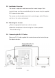
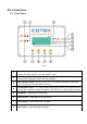
3.0 Introduction 3.1 Front Panel Fig. 3 1 LED Indicators - There are two LED indicators on the front panel that light solid to indicate the UNIT ON/OFF and CHG ON/OFF status. 2 LCD Display - The LCD display is used for setting up the system operation, as well as viewing current operating status and fault conditions. 3 UNIT ON/OFF Button - When user presses it, the remote and machine could work then remote must communication to machine.
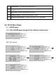
9 SHORE power - Set Inverter max current.(see 4.1) 10 UNIT readings - This item show DC、Temperature、AC INPUT and VAC OUT, FAULT condition. (see 4.2) 11 UNIT setup - Setting inverter parameter. (see 4.3) 12 REMOTE settings - Setting remote parameter. (see 4.4) 13 Operation mode indicator – indicate Power Share、INV、CHG mode 4.0 CR-20 Menu Maps 4.1 SHORE power. 4.2 Select SHORE power and press Enter Button as below frame. 4.3 UNIT readings.
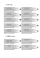
4.4 UNIT setup. 4.5 REMOTE setting.
5.0 System Status Messages 5.1 UNIT./CHG LED indicator UNIT ON/OFF CHG ON/OFF Soild Green Normal CHG mode ON Blink Green Bypass Soild Red Error NO Light CHG mode OFF 6.0 Warranty We guarantee this product against defects in materials and workmanship for a period of 24 months from the date of purchase and will repair or replace any defective Combi units if you directly returned them to us with postage paid.