
CR-8 User guide

1
User Guide For CR8 Remote Control
1. Features
Remote ON / OFF inverter operation
Ignition lockout information display and Return Override Function Acting
2. Specification
Input Voltage Range: 10.5 ~ 60 Vdc depends on inverter model
Operating Temperature Range : 0 ~ 40
Storage Temperature Range : -30 ~ 70
Stand-By Current Draw : < 40mA
Applicable Models : SP / SD / SE series
3. Introduction
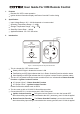
Figure 1. CR8 front panel and rear panel introduction
This is a simple ON / OFF remote control
Steady red LED light in dicates the Inverter is ON
Fast flashing red LED light indicates that it is in Return Override Function selection status
Slow flashing red LED light indicates that it is in Ignition Lockout Function selection status
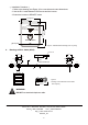
The wire JP1 is placed inside the remote controller and it is to indicate either Return Override
Function or Ignition Lockout Function
JP1 jumper “Open” – Return Override Function
JP1 jumper “Short” – Ignition Lockout Function
Please note that the default mode is OPEN
The wire must go with a 12 Volt 0.5A fuse with proper sizes
Connect the wire RJ-11 to the remote port in front of the panel
Ignition Lockout function The Ignition lockout function is to turn the Inverter OFF
when the auxiliary input wiring is connected to the ACC. (accessory), and 12 Volts is applied
Return Override Function The Return Override Function is to turn the Inverter ON
when the auxiliary input wiring is connected to the reverse gear Shift, and 12 Volts is applied
ON/OFF
PUSH
Blinking Slow
Ignition Lockout
Inverter Status
TO
INVERTER
AUX. +12
Solid Red
Blinking Fast
R.O.F Acting
Inverting
INVERTER REMOTE
(INTERNAL)
PIN
JUMPER