
Installation Guide


11
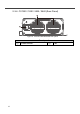
2-3-2. CX1215 / 1225 / 1235 / 2415 (Rear Panel)
Figure 7. CX1215/1225/1235/2415 rear panel
Front panel
① AC Inlet (IEC) ② Status LED
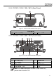
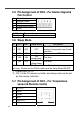
2-3-3. CX1250 / 1280 / 2425 / 2440 (Front Panel)
Figure 8. CX1250/1280/2425/2440 front panel
Front panel
① AC Inlet (IEC) ⑤ Status LED
② DC output - ⑥ CN2
③ DC output + ⑦ TEMP/CN3
④ Dip Switch 1 (S1) ⑧ CN4
Note: For detail description on item 4 (Dip Switch S1),
please refer to section 3-2
1
2
1
23
4
5 6 7 8