CX Series User’s Manual Manuel utilisateur série CX
Legal Provisions Copyrights 2017 COTEK Electronic IND. CO. All Rights Reserved. Any part of this document may not be reproduced in any form for any purpose without the prior written permission of COTEK Electronic IND. CO. For the conditions of the permission to use this manual for publication, contact COTEK Electronic IND. CO., LTD. In all related COTEK product activities, Neither COTEK Electronic IND. CO., LTD.
EN Table of Content 1. Important Safety Information 1 1-1. General Safety Precautions 1 1-2. Battery Precautions 2 2. Features 3 2-1. Battery Charging Curve 4 2-2. Specification 6 2-3. Mechanical Drawings 9 3. Product Description 13 3-1. Configurations 13 3-2. S1 Setting 14 3-3. Charging Status LED Indicator 15 3-4. Failure Indicator 15 3-5. Pin Assignment of CN2 – For Alarms Signal & Fan Control 16 3-6. Sleep Mode 16 3-7.
. Installing Converter / Charger 4-1. Battery charger connection diagram 21 23 5. Trouble Shooting 27 6. Warranty Statement 28 6-1. Warning 28 6-2.
1. Important Safety Information Warning! Before installing or using CX series power converter, you need to read following safety information carefully. 1-1. General Safety Precautions 1-1-1. For indoor use, do not expose CX-Series Battery Charger to water, mist, snow, or dust. To reduce the risk of fire, do not cover or obstruct the ventilation enclosure. 1-1-2. To avoid the risk of fire and electric shocks, make sure that existing wiring is in good electrical condition and not undersized. 1-1-3.
EN 1-2. Battery Precautions 1-2-1. If battery acid contacts your skin or clothing, wash it out with soap and water immediately. 1-2-2. If battery acid contacts your eyes, wash it out with cold running water for at least 20 minutes and get medical attention immediately. 1-2-3. Never smoke or make a spark or flame in the vicinity of the battery. 1-2-4. Do not drop metals on the battery. The resulting sparks or short-circuits on the battery or other electrical parts may cause an explosion. 1-2-5.
2.
EN 2-1. Battery Charging Curve 14.4 / 28.8 V 13.8 / 27.6 V 12.8 / 25.6 V 9.6 / 19.2 V 0V Current BULK(CC) ABSORPTION(CV) FLOAT RECONDITION FLOAT Maintain the battery at 100% charge condition PER-CHARGE Return amps = 6.25% of rated current Reconditioning the battery Stay at 13.8V / 27.6V 2 Weeks FLOAT 0.25 hours~24 hours Maintain the battery at 100% charge condition 14.4V / 28.
2-1-1. Bulk Stage (Constant Current) At the beginning of the charging process, the flat battery is charged at constant current (maximum charge current) until the battery voltage reaches the set charging voltage (Refer to 3-2 charging mode setting). 2-1-2. Absorption Stage (Constant Voltage) The absorption charging duration will depend on the battery status. Before moving to absorption stage, charger will wait for two minutes then charging at constant voltage until the battery is fully charged.
EN 2-2. Specification Model 14.4V / 14.7V (Select by S1 DIP switch) Standard Float Charge Voltage 13.8V / 13.5V (Select by S1 DIP switch) CX1250 CX1280 80A 15A 25A 35A 50A Main Output 1 2 2 3 3 ESB Output 1 1 1 -- -- 13.8V/2A 13.8V/2A 13.
Model Standard Boost Charge Voltage 28.8V / 29.4V (Select by S1 DIP switch ) Standard Float Charge Voltage 27.6V / 27V (Select by S1 DIP switch) 12.5A 25A 2 3 3 ESB Output -- -- -- ESB Output Voltage / Current -- -- -- Battery Charging Mode 3-stage charging capability IUOU Isolation Type Use active power MOSFET on each output terminal 12.
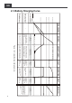
EN Charging current (%) 2-2-1. Charging Current vs. Ambient Temperature De-rating Curve 100% Normal 80% 40% S1 pin4 ON or CN2 pin4-5 Short 20% CR1 Sleep mode 10% -20°C 40°C 50°C Ambient Temperature Charging current vs. Ambient Temperature Figure 2. Charging current vs. Ambient temperature de-rating curve Charging current (%) 2-2-2. Charging Current vs. Input Voltage Temperature De-rating Curve 100% 50% 90 110 130 230 250 270 AC Voltage (V) Charging current vs. Input voltage Figure 3.
2-3. Mechanical Drawings CX1280, CX2440 CX1250, CX2425 CX1235 CX1215, CX1225, CX2415 C A E B D F Figure 4. Mechanical Drawings Model A (mm) B (mm) C (mm) D (mm) E (mm) F (mm) CX1215 243 54.2 135.0 183 6.5 72 CX1225 243 54.2 135.0 183 6.5 72 CX1235 263 56.7 150.0 183 6.5 72 CX1250 272 60.2 152.0 213 6.5 77 CX1280 312 65.2 182.0 213 6.5 77 CX2415 243 54.2 135.0 183 6.5 72 CX2425 272 60.2 152.0 213 6.5 77 CX2440 312 65.2 182.0 213 6.
EN 2-3-1. CX1215 / 1225 / 1235 / 2415 (Front Panel) 6 7 8 9 3 2 5 4 1 Figure 5. CX1215 front panel 6 7 8 9 3 2 5 4 1 Figure 6.
2-3-2. CX1215 / 1225 / 1235 / 2415 (Rear Panel) 2 1 Figure 7. CX1215/1225/1235/2415 rear panel AC Inlet (IEC) ① Front panel Status LED ② 2-3-3. CX1250 / 1280 / 2425 / 2440 (Front Panel) 5 6 7 8 4 3 2 1 Figure 8.
EN 2-3-4. CX1250 / 1280 / 2425 / 2440 (Rear Panel) 2 1 Figure 9.
3. Product Description Below models are available with COTEK Advanced Battery Charger CX Series: Model No. of supply battery CX1215 CX1225 / CX1235 CX1250 / CX1280 CX2415 CX2425 / CX2440 1 2 3 2 3 Support ESB (Extra Second Battery) Yes Yes No No No 3-1. Configurations 3-1-1.
EN Number A B C CX 1215 CX 1225 CX 1235 CX 1250 CX 1280 CX 2415 CX 2425 CX 2440 2pcs 1pcs 1pcs 3pcs 1pcs 1pcs 3pcs 1pcs 1pcs 5pcs 1pcs 1pcs 5pcs 1pcs 1pcs 3pcs 1pcs 1pcs 5pcs 1pcs 1pcs 5pcs 1pcs 1pcs 3-2. S1 Setting 3-2-1.
3-3. Charging Status LED Indicator Charging status Bulk-1 Bulk-2 Absorption-1 Absorption-2 Float LED Status Orange fast Orange slow Orange solid Green solid Green flash LED color change by the status change 3-4. Failure Indicator Failure status LED Status Input or Output Red solid Temperature Red fast Battery voltage Red slow Fan abnormality ESB Failure Red light flash twice Red slow every 2 sec.
EN 3-5. Pin Assignment of CN2 – For Alarms Signal & Fan Control 1 2 3 4 5 Normally closed Normally open COM Sleep mode control GND 4-5 Short 4-5 Open Sleep mode on Sleep mode off 3-6.
3-8. Pin Assignment of CN4 – For Remote control 1 R_VCC 2 BAT- 3 NC. 4 BAT- 5 DATA I/O 6 NC. 3-9. Pin Assignment of ESB Connectors – For CX1215/1225/1235 + VCC - GND 3-10. Temperature Compensation CX12XX series model 15.0 14.7VDC Charging voltage in V 14.5 14.2VDC 14.0 13.8VDC 13.5 Abs orp tion Flo 12Volt system: -10mV / 0.5oC at 13.4VDC -3.33mV / oC per cell 13.0 12.5 Battery voltage 12.
EN CX24XX series model 30.0 29.4VDC Charging voltage in V 29.0 Abs orp tion 28.4VDC 28.0 Flo 27.6VDC 27.0 24Volt system: -20mV / 0.5oC at 26.8VDC -3.33mV / C per cell o 26.0 25.0 Battery voltage 24.0 U Rer 20oC o 52 C -30 -20 -10 0 5 10 20 30 40 50 60 Temperature compensation characteristic (charge voltage versus temperature) Battery temperature oC ※ In the CV=29.4V and float=27.6V situation. Please follow this rule in other situations. Figure 11.
3-12. Battery Charger Selection (Reference only) y 12 Volt Battery COTEK Model Battery capacity range CX1215 CX1225 CX1235 CX1250 CX1280 50~80Ah 80~125Ah 125~175Ah 175~250Ah 250~400Ah Estimated charging time 6~24 6~24 6~24 6~24 6~24 The above suggested battery charger selection is based on battery capacity multiply 0.2~0.3. Example: 100Ah battery * 0.2 / 0.3 = 20A~30A in this case please select CX1225.
EN 3-14. Fan speed duty description The fan determined by load and heat sink temperature. 1. Fan speed 100%: comply with one of the following conditions a. Load ≧ 75% b. Load ≧ 50% and heat sink temperature ≧ 50℃ c. Heat sink temperature ≧ 75℃ 2. Fan speed duty 50%: a. Heat sink temperature ≧ 67.5℃ or b. Set CX to sleep mode by setting DIP4 (Refer to 3-2) when 1. a, b, or c applies 3. Fan speed duty 0%: a. Load < 75% and heat sink temperature < 35℃ or b.
4. Installing Converter / Charger When selecting the installation location, observe the following instructions: y Do not install the charger in following situations: In wet environments In dusty environments In the vicinity of combustible materials In areas where there is a danger of explosions y The place of installation must be well ventilated. A ventilation system must be available for installations in small, enclosed space. The clearance around the device must be at least 25cm.
EN For installation and mounting you will need the following tools: y Pen for marking y Drill bit set y Drill y Screwdriver To secure the charger in place you will need: y Machine bolts (M4) with washers and self-locking nuts or y Self-tapping screws or wood screws Fasten the charger as follow: y Hold the charger against the installation location y Mark the fastening points y Fasten the charger with one screw through each hole in the holders 22
4-1. Battery charger connection diagram Model CX1215 Description Connection diagram 15A MAX Fuse Fuse Temp. Sensor Remote Control 12V Battery DC LOAD Extra Second Battery Fuse Voltage:32V, Fuse Current:23A CX1225 CX1235 ‧I1+I2 CX1225: 25A MAX I1 I2 CX1235: 35A MAX Fuse Fuse 12V Battery Temp.
EN Model CX2415 Description Connection diagram I1 ‧I1+I2 12.5A MAX I2 Fuse Temp. Sensor Remote Control 24V Battery DC LOAD Fuse Voltage:32V, Fuse Current:23A CX1225 CX1235 ‧I1 or I2 CX1225: 25A MAX I1 I2 CX1235: 35A MAX 12V Battery Fuse Fuse Fuse 12V Battery Temp.
Model CX2415 Description Connection diagram ‧I1 or I2 12.5A MAX I1 I2 Fuse Fuse 24V Battery Temp. Sensor 24V Battery Remote Control DC LOAD Fuse Voltage:32V, Fuse Current:23A CX1250 CX1280 ‧I1+I2+I3 CX1250: 50A MAX I2 I3 Fuse CX1280: 80A MAX I1 12V Battery Temp.
EN Model CX2425 CX2440 Description ‧I1+I2+I3 CX2425: 25A MAX I1 I2 I3 Fuse CX2440: 40A MAX Connection diagram 24V Battery Temp.
5. Trouble Shooting LED display Cause Remedy Battery under Check the battery. Red, slowly voltage or battery Switch the battery charger off and on flashing overload again. Defective battery Replace the battery Improve the ventilation of the battery charger or battery. Red, rapidly flashing Overheating Make sure that no ventilation openings are covered. If necessary, reduce the ambient temperature.
EN 6. Warranty Statement 6-1. Warning Warning! Do not open or disassemble the Converter / Charger. Attempting to do so may cause risk of electrical shock or fire. 6-2. Warranty We guarantee this product against defects in materials and workmanship for a period of 24 months from the date of purchase. In case you need to repair or replace any defective power inverters, please contact COTEK local distributor.
FR Table des matières 1. INFORMATIONS IMPORTANTES, SECURITE 31 1-1. Précautions générales 31 1-2. Précautions avec les batteries 32 2. PRESENTATION 33 2-1. Courbes de charge 34 2-2. Caractéristiques 36 2-3. Schémas mécaniques 39 3. DESCRIPTION DU PRODUIT 43 3-1. Configurations 43 3-2. Paramètres interrupteur DIP S1 44 3-3. Témoin de charge (LED) 45 3-4. Témoin de défaut (LED) 45 3-5. Connecteur CN2 – Signal d’alarme & contrôle du ventilateur 46 3-6. Mode veille 46 3-7.
4. INSTALLATION DU CHARGEUR 4-1. Connexions à la batterie 51 53 5. RECHERCHE DE PANNES 57 6. GARANTIE 58 6-1. Avertissement 58 6-2.
1. Informations importantes, sécurité Avertissement ! Prendre le temps de lire et de comprendre les informations contenues dans ce manuel avant d’installer le chargeur série CX. 1-1. Précautions générales 1-1-1. Conçu pour être utilisé en intérieur, le chargeur CX ne doit pas être exposé à l’eau, à la condensation, à la neige ou à la poussière. Pour réduire les risques d’incendie, ne pas couvrir ni obstruer les orifices de ventilation. 1-1-2.
FR 1-2. Précautions avec les batteries 1-2-6. En cas de contact de l’électrolyte avec la peau ou les vêtements, laver immédiatement à l’eau savonneuse. 1-2-7. Si les yeux sont atteints, laver à l’eau courante pendant 20 minutes minimum et consulter immédiatement un médecin. 1-2-8. Ne jamais fumer, créer une étincelle ou utiliser une flamme à proximité de la batterie. 1-2-9. Ne pas laisser tomber d’objet métallique sur la batterie.
2.
FR 2-1. Courbes de charge 14.4 / 28.8 V 13.8 / 27.6 V 12.8 / 25.6 V 9.6 / 19.2 V 0V Courant BULK(CC) ABSORPTION(CV) FLOAT RECONDITION 2 semaines FLOAT 2 min~8 heures BULK(CC) 2 semaines Reconditionnement de la batterie Se maintient à 13,8V / 27,6V Maintient le niveau de charge à 100% PER-CHARGE Return amps = 6.25% of rated current 85 min 0.
2-1-1. Phase de Boost – Bulk Stage (courant constant) Au début du cycle de charge, la batterie à plat est chargée à courant constant (au courant de charge max), jusqu’à ce que la tension atteigne le seuil de fin de phase (voir $ 3-2-1 Paramètres). 2-1-2. Phase d’absorption – Absorption Stage (tension constante) La durée d’absorption dépend de l’état de la batterie. Il y a une temporisation de 2 minutes avant que le chargeur ne bascule en phase d’absorption.
FR 2-2. Caractéristiques Modèle 14.4 V / 14.7 V (choix via interrupteur DIP S1) Tension d’entretien (Float) 13.8 V / 13.5 V (choix via interrupteur DIP S1) CX1250 CX1280 80 A 15 A 25 A 35 A 50 A Sortie(s) 1 2 2 3 3 Sortie supplémentaire (ESB) 1 1 1 -- -- 13.8 V / 2 A 13.8 V / 2 A 13.
Modèle Tension de Boost 28.8 V / 29.4 V (choix via interrupteur DIP S1) Tension d’entretien (Float) 27.6 V / 27 V (choix via interrupteur DIP S1) CX2440 12.5 A 25 A Sortie(s) CA 2 3 3 Sortie supplémentaire (ESB) -- -- -- -- -- -- Tension/Courant sortie suppl.
FR Charging current (%) 2-2-1. Courant de charge vs température ambiante – Courbe de déclassement 100% Normal 80% 40% S1 pin4 ON or CN2 pin4-5 Short 20% CR1 Sleep mode 10% -20°C 40°C 50°C Ambient Temperature Charging current vs. Ambient Temperature Schéma 2. Courant de charge vs température ambiante – Courbe de déclassement Charging current (%) 2-2-2. Courant de charge vs tension d’entrée – Courbe de déclassement 100% 50% 90 110 130 230 250 270 AC Voltage (V) Charging current vs.
2-3. Schémas mécaniques CX1280, CX2440 CX1250, CX2425 CX1235 CX1215, CX1225, CX2415 C A E B D F Schéma 4. Schémas mécaniques Modèle A (mm) B (mm) C (mm) D (mm) E (mm) F (mm) CX1215 243 54.2 135.0 183 6.5 72 CX1225 243 54.2 135.0 183 6.5 72 CX1235 263 56.7 150.0 183 6.5 72 CX1250 272 60.2 152.0 213 6.5 77 CX1280 312 65.2 182.0 213 6.5 77 CX2415 243 54.2 135.0 183 6.5 72 CX2425 272 60.2 152.0 213 6.5 77 CX2440 312 65.2 182.0 213 6.
FR 2-3-1. CX1215 / 1225 / 1235 / 2415 (Panneau avant) 6 7 8 9 3 2 5 4 1 Schéma 5. CX1215 – Panneau avant 6 7 8 9 3 2 5 4 1 Schéma 6. CX1225/1235/2415 – Panneau avant ① ② ③ ④ ⑤ Panneau avant Entrée CA (IEC) ⑥ Sortie supplémentaire ⑦ (sur CX 1215/1225/1235) Négatif sortie CC (-) ⑧ Positif sortie CC (+) ⑨ Interrupteur DIP 1 (S1) Témoin d’état (LED) CN2 TEMP/CN3 CN4 Note: pour une description détaillée de l’interrupteur DIP S1, voir § 3-2.
2-3-2. CX1215 / 1225 / 1235 / 2415 (Panneau arrière) 2 1 Schéma 7. CX1215/1225/1235/2415 – Panneau arrière Entrée CA (IEC) ① Panneau arrière Témoin d’état (LED) ② 2-3-3. CX1250 / 1280 / 2425 / 2440 (Panneau avant) 5 6 7 8 4 3 2 1 Schéma 8.
FR 2-3-4. CX1250 / 1280 / 2425 / 2440 (Panneau arrière) 2 1 Schéma 9.
3. Description du produit Étendue de la gamme de chargeurs COTEK série CX : Modèle Sortie supplémentaire (ESB) Oui Oui Non Non Non Nb de sortie(s) CX1215 CX1225 / CX1235 CX1250 / CX1280 CX2415 CX2425 / CX2440 1 2 3 2 3 3-1. Configurations 3-1-1. Accessoires en standard Repère A B Connecteur cuivre Description C D Vis Câble alim.
FR Quantités A B C CX 1215 CX 1225 CX 1235 CX 1250 CX 1280 CX 2415 CX 2425 CX 2440 2 1 1 3 1 1 3 1 1 5 1 1 5 1 1 3 1 1 5 1 1 5 1 1 3-2. Paramètres interrupteur DIP S1 3-2-1. Paramètres État 1 2 3 4 Basculement charge CC/CV* ON OFF X X OFF OFF ON ON X X X X ON OFF OFF ON OFF ON X X OFF OFF OFF OFF ON ON ON ON X X X X X X X X X X ON OFF Tension de Float Mode alimentation (courant limité) Cde à distance Mode veille 12 V / 24 V 12 V / 24 V Seuil CC/CV Float 14.4 V / 28.8 V --14.7 V / 29.
3-3. Témoin de charge (LED) Phase État de la LED Bulk-1 Orange, flashs rapides Bulk-2 Orange, flashs lents Absorption-1 Orange, fixe Absorption-2 Vert, fixe Float Vert, flashs La couleur de la LED varie en fonction de la phase en cours 3-4. Témoin de défaut (LED) Défaut État de la LED Entrée ou Sortie Rouge, fixe Température Rouge, fixe Tension batterie Rouge, flashs lents Ventilateur Sortie supplémentaire Rouge, flashs doubles Rouge, flashs toutes les 2 s.
FR 3-5. Connecteur CN2 – Signal d’alarme & contrôle du ventilateur 1 2 3 4 5 Normalement fermé Normalement ouvert COM Contrôle mode veille Terre 4-5 avec cavalier 4-5 sans cavalier Mode veille activé (ON) Mode veille désactivé (OFF) 3-6.
3-8. Connecteur CN4 – Commande à distance (R) 1 R_VCC (Positif VCC) 2 BAT- (négatif batterie) 3 NC (contact normalement fermé) 4 BAT- (négatif batterie) 5 DATA I/O (entrée/sortie des données) 6 NC (contact normalement fermé) 3-9. Sortie supplémentaire (batterie) – Modèles CX1215/1225/1235 uniquement + VCC (Positif VCC) - GND (terre) 3-10. Compensation en température Modèles CX12XX 15.0 14.7VDC Charging voltage in V 14.5 14.2VDC 14.0 13.8VDC 13.
FR Modèles CX24XX 30.0 29.4VDC Charging voltage in V 29.0 Abs orp tion 28.4VDC 28.0 Flo 27.6VDC 27.0 24Volt system: -20mV / 0.5oC at 26.8VDC -3.33mV / C per cell o 26.0 25.0 Battery voltage 24.0 U Rer 20oC o 52 C -30 -20 -10 0 5 10 20 30 40 50 60 Temperature compensation characteristic (charge voltage versus temperature) Battery temperature oC ※ In the CV=29.4V and float=27.6V situation. Please follow this rule in other situations. Schéma 11.
3-12. Choix d’un chargeur (pour info) y Batterie 12 V Chargeur Capacité de la batterie CX1215 CX1225 CX1235 CX1250 CX1280 50~80 A.h 80~125 A.h 125~175 A.h 175~250 A.h 250~400 A.h Estimation du temps de charge 6~24 6~24 6~24 6~24 6~24 Pour cette estimation nous avons multiplié la capacité par 0.2~0.3. Exemple pour une batterie 100 A.h : 100 x 0.2 / 0.3 = 20 A~30 A, choisir le modèle CX1215. y Batterie 24 V Chargeur Capacité de la batterie CX2415 CX2425 CX2440 50~80 A.h 80~125 A.h 125~200 A.
FR 3-14. Régime du ventilateur Le ventilateur est asservi à la charge et à la température (dissipateur). 1. Plein régime (100%) : a. Charge ≧ 75% b. Charge ≧ 50% et température du dissipateur ≧ 50°C c. Température du dissipateur ≧ 75°C 2. ½ régime (50%) : a. Température du dissipateur ≧ 67.5°C ou b. Le chargeur CX bascule en mode veille en fonction de la configuration du DIP4 (voir § 3-2) lorsque 1. a, b, or c survient 3. Arrêt (0%) : a. Charge < 75% et température du dissipateur < 35°C ou b.
4. Installation du chargeur Tenir compte des points suivants pour le choix de l’emplacement : y Ne pas installer le chargeur: Dans un environnement humide Dans un environnement exposé à des poussières À proximité de matériaux inflammables Dans un environnement présentant des risques d’explosion y L’emplacement choisi doit être correctement aéré. En lieu clos, prévoir un système de ventilation. Prévoir un dégagement minimum de 25 cm tout autour de l’appareil.
FR Prévoir les outils suivants : y Marqueur y Jeu de forets y Perceuse y Tournevis Quincaillerie : y Écrous M4 avec rondelle et écrous autobloquants ou y Vis auto-taraudeuses ou vis à bois Monter le chargeur de la manière suivante : y Poser le chargeur à l’emplacement choisi y Utiliser les orifices pour marquer les trous de fixation y Utiliser des vis ou boulons adéquats en fonction de la nature du support 52
4-1. Connexions à la batterie Modèle CX1215 Description Schéma de câblage 15 A max Fuse Fuse Temp. Sensor 12V Battery Remote Control DC LOAD Extra Second Battery Remote Control DC LOAD Extra Second Battery Fusible:32 V 23 A CX1225 CX1235 I1+I2 CX1225: 25 A max I1 I2 CX1235: 35 A max Fuse Fuse 12V Battery Temp.
FR Modèle CX2415 Description Schéma de câblage I1 I1+I2 12.5 A max I2 Fuse Temp. Sensor Remote Control 24V Battery DC LOAD Fusible:32 V 23 A CX1225 CX1235 I1 ou I2 CX1225: 25 A max I1 I2 CX1235: 35 A max 12V Battery Fuse Fuse Fuse 12V Battery Temp.
Modèle CX2415 Description Schéma de câblage I1 ou I2 12.5 A max I1 I2 Fuse Fuse 24V Battery Temp. Sensor 24V Battery Remote Control DC LOAD Fusible:32 V 23 A CX1250 CX1280 I1II2II3 CX1250: 50 A max I2 I3 Fuse CX1280: 80 A max I1 Temp.
FR Modèle CX2425 CX2440 Description Schéma de câblage I1+I2+I3 CX2425: 25 A max I1 I3 Fuse CX2440: 40 A max I2 Temp.
5. Recherche de pannes LED Cause Remède Tension batterie basse ou surcharge Vérifier l’état de la batterie. Éteindre puis redémarrer le chargeur. Batterie défectueuse Remplacer la batterie. Rouge, flashs rapides Surchauffe Améliorer la ventilation du chargeur ou de la batterie. S’assurer que les orifices de ventilation ne sont pas obstrués. Si possible, réduire la température ambiante. Rouge, fixe Court-circuit ou inversion de polarités Refaire les branchements en respectant les polarités.
FR 6. Garantie 6-1. Avertissement Attention ! Ne pas ouvrir ni démonter le chargeur. Risques de chocs électriques voire d’incendie. 6-2. Garantie Nous garantissons ce produit contre tout défaut de matériaux et de main-d’œuvre pour une durée de 24 mois. Pour toute demande de service après-vente, merci de contacter votre distributeur local. Cette garantie sera considérée comme nulle si l’appareil n’a pas été utilisé de manière correcte, s’il a été modifié ou s’il a été endommagé accidentellement.
No.33, Sec. 2, Renhe Rd., Daxi Dist., Taoyuan City 33548, Taiwan Phone:+886-3-3891999 FAX:+886-3-3802333 http:// www.cotek.com.tw 2017.01.