
SC Series User Manual

14
EN
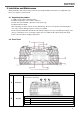
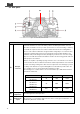
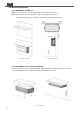
3-3. Rear panel
Fig. 5
:
SC series Rear panel introduction
Rear panel
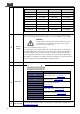
A
DC input
connector
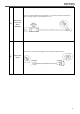
Follow the instructions to connect the battery cables to the DC input terminals of the unit.
The cables should be as short as possible (less than 6 feet / 1.8 meters ideally) so that they
can handle the required current in accordance with the Electrical Codes and Regulations.
The size of the cable should be thick enough to limit the voltage drop to less than 2% when
carrying the maximum input current to prevent frequent low-input voltage warnings, and
shutdown. UVP (Under Voltage Protection) warning may result if there is excessive voltage
drop across the DC cables between the batteries and the unit. Increasing your DC cable size
will help improve the situation.
Batteries are capable of providing very large currents in case of short circuit. In case there is
a short circuit in the cable run between the batteries and the input terminals of the unit, it will
result in overheating / melting of the cables and consequent risk of fire and injury, to prevent
possibility of this hazard, use Very Fast Acting DC Fuse in line with the positive cable. The
fuse should be as close to the positive battery terminal as possible.
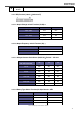
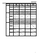
The following sizes of cables and fuses are recommended for up to 6 ft. distance between
the batteries and the unit.
Model No.
Wire AWG
Inline Fuse
External Fuse
SC1200-124
SC1200-224
#6
100A
>100A
SC1200-112
SC1200-212
SC2000-124
SC2000-224
#2
200A
>200A
SC2000-112
SC2000-212
#2/0
400A
>400A
B
Auxiliary DC
output Fuse
Second charger limit current protection.
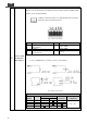
C
Auxiliary DC
output
SC series has a second charger output connector can be used to give a maintenance of a
small battery. Maximum current is 20A.
G