
Product Manual


15
3. Introduction
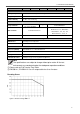
B. Power device leaving saving mode(re-start)
Restart threshold = rate power x setting % x 2~3
In case the power over the restart threshold, the power device will re-start and
provide the AC power.
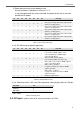
S1
S2
S3
S4
S5
S6
S7
S8
Scenario
X
X
X
0
0
0
0
X
Power saving DISABLE
X
X
X
1
1
0
0
X
Go in power saving mode when output load is
under 4% of rating power
X
X
X
0
0
1
0
X
Go in power saving mode when output load is
under 5% of rating power
X
X
X
1
0
1
0
X
Go in power saving mode when output load is
under 6% of rating power
X
X
X
0
1
1
0
X
Go in power saving mode when output load is
under 7% of rating power
X
X
X
1
1
1
0
X
Go in power saving mode when output load is
under 8% of rating power
1=ON / 0=OFF
Table 7. Power saving mode set-up
3-3-3. S4~S6 Set-up for parallel application
S1
S2
S3
S4
S5
S6
S7
S8
Scenario
X
X
X
0
0
0
1
X
Master (0°); "R" Phase
to be used for 1Ø 3W output in series
connection(Master) or 3Ø 4W output
connection("R" Phase)
X
X
X
0
0
1
1
X
Slave (0°) with current sharing
to be used in parallel connection only
X
X
X
0
1
1
1
X
Slave (180°), to be used for 1Ø 3W output in
series connection(L-NN-L)
X
X
X
1
0
0
1
X
Slave (-120°), "S" Phase
to support "S" Phase be(-120°) in 3Ø 4W
output connection
X
X
X
1
0
1
1
X
Slave (120°), "T" Phase
to support "T" Phase be(120°) in 3Ø 4W
output connection
X
X
X
1
1
1
1
X
Disable parallel function
1=ON / 0=OFF
Table 8. Parallel application set-up
3-3-4. Parameter select: “S8” select SD’s parameter setting by dip switch or LCM port
Set Value
S8
LCM port
0
DIP switch
1
1=ON / 0=OFF
Table 9. Parameter select
3-4. DC Input - (please refer to DC wiring connections on P.20)