
SD3500 Manual


13
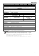
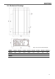
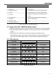
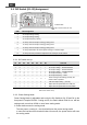
Front Panel / Rear Panel
1
Power ON/OFF/REMOTE (Main) switch
10
AC output socket
2
Status LED
11
Reset Button
3
Dip Switch (S1~S8)
12
CAN2 Port (only to be used in parallel mode)
4
DC Input -
13
CAN1 Port (only to be used in parallel mode)
5
DC Input +
14
LCM Port (Connection for LCD remote control
panel)
6
Chassis Ground
15
Green terminal (Remote and Parallel select)
7
AC Output
16
Remote / RS-232 port
8
By-pass AC Input
17
FAN
9
AC input circuit breaker
Table 3. SD front panel / rear panel introduction
3-1. Power ON / OFF / REMOTE (Main) switch
A. Before installing the inverter, please ensure the main switch is in the OFF position.
B. Before using the remote unit, please ensure the main switch is in the REMOTE
position.
C. Main switch ON / OFF will not control AC Grid input, therefore for any
maintenances please remove the AC Grid connection to prevent damage of SD
series, then turn off the Main switch to OFF position for maintenance service.
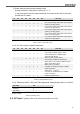
3-2. LED Indicator
Green LED
LED Signal
Status
Solid
Power OK
Slow Blink
Power Saving
Intermittent Blink
Bypass
Orange LED
LED Signal
Status
Fast Blink
OVP
Slow Blink
UVP
Red LED
LED Signal
Status
Intermittent Blink
OTP
Fast Blink
OVP- Shut-down
Slow Blink
UVP- Shut-down
Solid
OLP
Intermittent Blink
Fan Failure
Intermittent Blink
Component Failure
Table 4. SD LED indicator