
Installation Manual


16
3-5. DC Input + (please refer to DC wiring connections on P.20)
3-6. Chassis Ground:Connect the wire # 8 AWG to vehicle chassis
WARNING!
Operating the inverter without a proper ground connection may cause electrical
safety hazard.
3-7. AC Output (Please refer to hard wiring installation on P.21)
3-8. By-pass AC input (please refer to hard wiring installation on P.21)
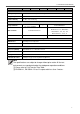
3-9. AC input circuit breaker
The AC input circuit breaker protects the model from overload. When an overload
condition exists, the circuit breaker stops supplying output AC grid power. To reset it,
push the circuit breaker switch then the model will be back in normal operation. The
source fault should be corrected before you reset it.
3-10. AC output socket (please refer to 4-2-3. on P.24)
3-11. Reset Button (only to be used for Ethernet interface)
The Reset Button is to be used to resume the IP address to factory default value:
IP:192.168.100.181
Subnet Mask:255.255.255.0
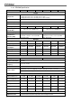
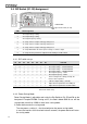
3-12. CAN1 and CAN2 Port (only to be used in parallel mode)
Figure 9. CAN1 and CAN2 port
1. Before using parallel mode, you need to ensure the green terminal’s parallel jump
status is set to ON.
2. Use the RJ-45 line (RJ-45 network cable:parallel connection) to link one of the
SD Series CAN1 (CAN2) port to the other CAN1 (CAN2) port.
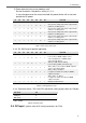
PIN#
LCM port
CAN1 port
CAN2 port
1
CANH
CAN_H
CAN_H
2
CANL
CAN_L
CAN_L
3
P1
Reserved
Reserved
4
VCC-
Reserved
Reserved
5
VCC+
Reserved
Reserved
6
DIS
Reserved
Reserved
7
5VS-
RND
RND
8
5VS+
Reserved
Reserved
Table 10. LCM, CAN1, CAN2 port
:
PIN number and signal description