
Installation Guide


6
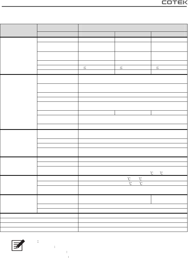
2-3-2. SP-1000 Specification
Electrical
Specification Model No.
Item S
P
-1
0
0
0
-112 S
P
-1
0
0
0
-124 S
P
-1
0
0
0
-14
8
Input
Characteristics
Voltage 12VDC 24VDC 48VDC
Input Over-Voltage
Protection
M
16.5 ± 0.3VDC 33 ± 0.5VDC 66 ± 1.0VDC
Input Under-Voltage
Protection
10.5 ± 0.3VDC 21 ± 0.5VDC 42 ± 1.0VDC
Voltage Range 10.5~16.5 VDC 21~33 VDC 42~66 VDC
No Load Current 1.5A @12VDC 0.8A @24VDC 0.5A @48VDC
Power Saving Mode <0.1A @12VDC <0.06A @24VDC <0.05A @48VDC
Output
Characteristics
Continuous Output
Power
1000 VA (± 3%)
Maximum output
Power (1Min)
> 1000 VA~1150 VA (100%~115%)
Surge Power (1Sec) < 1750 VA
Frequency 50 / 60 Hz ± 0.5% (Dip Switch Selectable)
Output Voltage
100 / 110 / 115 / 120 VAC (± 5%)
(Dip Switch Selectable)
Efficiency max. 92% 93% 93%
Short-Circuit
Protection
1 Sec Shutdown
Output Waveform
Pure Sine Wave (THD < 5%@ Normal Load)
N
Signal and Control
Remote Controller
Panel Unit
CR-8 / CR-16 (optional)
LED Indicator Red / Orange / Green LED
Dry Contact Terminal By a relay
Remote Control
Terminal
6-port Green terminal (for inverter ON / OFF)
Protection
Input Protection Over / Under Voltage, Reverse Polarity (Internal Fuse)
AC Output Protection Short-Circuit, Overload
Others
Over / Under Temperature Protection
(by Heat sink Temperature +80
/-20 )
Environment
Operating Temp.
-20
~40
O
Storage Temp. -30 ~70
Storage Temp. &
Humidity
10 ~95% RH
Safety & EMC
Safety Standards
Certified UL 458
(UL only for GFCI receptacles)
----
EMC standards Certified FCC class B
E-mark ----
Dimension(WxHxD) 200mm X 83mm X 372mm
Weight 3.26 KG
Cooling Temperature & Load Controlled cooling Fan
AC Transfer Function Accessories TR-40 (optional)
Table 3. SP-1000 for Output 100/110/115/120 VAC Specification.
Note
M Voltage range Please refer to Figure 1
N Normal load Condition
Vin =12.5V/25V/50V, Vo=100/110/115/120 VAC 80% Full load (PF=1.0)
O Operating temperature
Please refer to Figure 2