
Installation Manual


19
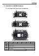
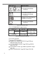
3-1-1. Main Switch
The 3-stage switch is for turning on, turning off and
remote mode.
3-1-2. LED Indicator
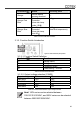
3-1-2-1. Input voltage level: to display Input Voltages
LED status DC 12V DC 24V DC 48V
Red < 11.0V < 22.0V < 44.0V
Orange 11.0 ~ 11.5V 22.0 ~ 23.0V 44.0~46.0V
Green 11.5 ~ 15.0V 23.0 ~ 30.0V 46.0~60.0V
Orange 15.0 ~ 15.5V 30.0 ~ 31.0V 60.0~62.0V
Red >15.5V >31.0V >62.0V
Table 15. Input Voltage Level LED Indicator
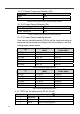
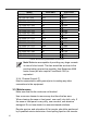
3-1-2-2. Output Load Level to display AC Loads (PF=1)
LED status Green Orange Red
SP-700 0 ~ 700 VA 700 ~ 805 VA > 805 VA
SP-1000 0 ~ 1000 VA 1000 ~ 1150 VA > 1150 VA
SP-1500 0 ~ 1500 VA 1500 ~ 1725 VA > 1725 VA
SP-2000 0 ~ 2000 VA 2000 ~ 2300 VA > 2300 VA
SP-3000 0 ~ 3000 VA 3000 ~ 3450 VA > 3450 VA
SP-4000 0 ~ 4000 VA 4000 ~ 4600 VA > 4600 VA
Table 16. Output Load Level LED Indicator
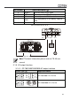
3-1-2-3. Inverter Status to display Fault condition
LED status Status Recovery point
Green Normal
Red
Over Current
Protection / Over
Load Protection
(AC output
short-circuit and
over load)
Red Blink
Under Voltage
Protection
(Input DC voltage
under spec)
12.5V @ DC12V system
25V @ DC24V system
50V @ DC48V system
Red Fast Blink
Over Voltage
Protection
(Input DC voltage
over spec)
14.5V @ DC12V system
29V @ DC24V system
58V @ DC48V system