
Installation Manual


22
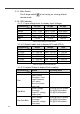
Pin Number Signal Description
4 Bypass Transfer Relay Driver Signal
5 12V Internal power for TR40 controller
6 5V Internal power for TR40 controller
7
GND
The same polarity as the battery negative
side
8 Reserved --
Table 24. SP Series TRC Port : RJ-45.
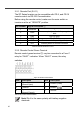
Figure 11. Wiring between SP series and TR-40
Note! The detail information please refer to TR-40 user
manual
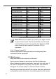
3-1-5. AC output Interface
3-1-5-1. SP-700/1000/1500/2000 AC output interface
Socket Type Applicable Model
SP-700/1000-112/124/148
SP-1500/2000-112/124/148
D
TRC
TRC
Inverter
Input
AC
Input
SP Series
TR-40
Load
AC
Output
Output
Breaker
North America (GFCI) NEMA 5-15R
North America (GFCI) NEMA 5-15R