
Installation Manual


27
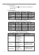
Model Wire AWG Inline fuse
SP-700-112 / 212 #6 150A
SP-700-124 / 224 #10 80 A
SP-700-148 / 248 #16 50 A
SP-1000-112 / 212 #4 225A
SP-1000-124 / 224 #8 125A
SP-1000-148 / 248 #14 80A
SP-1500-112 / 212 #1 350A
SP-1500-124 / 224 #6 175A
SP-1500-148 / 248 #10 90A
SP-2000-112 / 212 #1/0 500A
SP-2000-124 / 224 #4 225A
SP-2000-148 / 248 #8 150A
SP-3000-112 / 212 #4/0 700A
SP-3000-124 / 224 #1 350A
SP-3000-148 / 248 #6 175A
SP-4000-124 / 224 #1/0 500A
SP-4000-148 / 248 #4 275A
Table 30. SP Series Wiring Cable diameter and Inline Fuse
Note! Batteries are capable of providing very large currents
in case of short circuit. The fuse should be as close to the
positive battery terminal as possible. Use Bussmann ANN
series fuses (will also require Fuse Block 4164) or
equivalent.
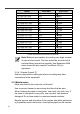
3-2-4. Chassis Ground
③
Must be connected to earth ground prior to making any other
connections to the equipment.
3-3. Maintenance
Make sure that the fan vents are not blocked.
Use a vacuum cleaner to remove any dust from the fan area
When cleaning the case or front panel, use a soft, dry cloth, only. If
the case or front panel is very dirty, use a neutral, non-abrasive
detergent. Do not use alcohol or ammonia based solutions.
Regular service, and relocation of the inverter, should be performed
by a qualified service technician. Avoid spilling liquid on the inverter.