
Datasheet


RI-02 Series Dry Reed Switch
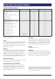
Technical Specications
Parameters Test Conditions Units RI-02
Operating Characteristics
Operate Range AT 7-21
Release Range AT 3-16
Operate Time - including Bounce (typ.) ms 0.30
Bounce Time (typ.) ms 0.10
Release Time (max)
μs
70
Resonant Frequency (typ.) Hz 10800
Electrical Characteristics
Switched Power (max) W 10
Switched Voltage DC (max) V 200
Switched Voltage AC, RMS value (max) V 140
Switched Current DC (max) mA 500
Switched Current AC, RMS value (max) mA 500
Carry Current DC (max) A 0.5
Breakdown Voltage (min) V 200 - 230
Contact Resistance (initial max.) mΩ 150
Contact Resistance (initial typ.) mΩ 120
Contact Capacitance (max) without test coil pF 0.3
Insulation Resistance (min) RH ≤ 45% MΩ 10
6
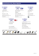
mounted in any position.
Shock
e switches are tested in accordance with “IEC 68-2-27”,
test Ea (peak acceleration 100 G; half sinewave; duration
11ms). Such a shock will not cause an open switch (no
magnetic eld present) to close, nor a switch kept closed
by an 80 AT coil to open.
Vibration
e switches are tested in accordance with “IEC 68-2-26”,
test Fc (acceleration 10G; below cross-over-frequency 57
to 62 Hz; amplitude 0.75 mm; frequency range 10 to
2000 Hz; duration 90 minutes.) Such a vibration will not
cause an open switch ( no magnetic eld present) to close,
nor a switch kept closed by an 80 AT coil to open.
Mechanical Strength
e robustness of the terminations is tested in accordance
with “IEC 68-2-21”, test Ua1 (load 10 N).
Operating and Storage Temperature
Operating ambient temperature; min: -55°C; max:
+125°C. Storage temperature; min: -55°; max: +125°C.
Note: Temperature excursions up to 150°C may be
permissible. For more information contact your nearest
Comus Group sales oce.
Soldering
e switch can withstand soldering heat in accordance
with “IEC 68-2-20”, test Tb, method 1B: solder bath at
350 ± 10°C for 3.5 ± 0.5 s. Solderability is tested in acc
ordance with “IEC 68-2-20” test Ta, method 3: solder
globule temperature 235°C; ageing 1b: 4 hours steam.
Welding
e leads can be welded.
Mounting
e leads should not be bent closer than 1 mm to the
glass-to-metal seals. Stress on the seals should be avoided
Care must be taken to prevent stray magnetic elds from
inuencing the operating and measuring conditions.
• As part of the company policy of continued product improvement, specications
may change without notice.Our sales ofce will be pleased to help you with the
latest information on this product range and the details of our full design and
manufacturing service. All products are supplied to our standard conditions of
sale unless otherwise agreed in writing.
USA Tel: +(1)973 777 6900 / Fax: +(1) 973 777 8405 ▪ Belgium Tel: + 32 (0)12 390400
Page 2 of 3