
User's Guide


9
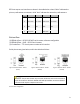
RF Ports map to wan interfaces as shown in the table below, where “Main” indicates the
primary radio antenna connector, while “Aux” indicates the secondary radio antenna.
RF Port
L8N
LW
8NW
8W
1
wan_a Main
wan_a Main
wan_b Main
wan_b Main
2
wan_a Aux
wan_a Aux
wan_b Aux
wan_b Aux
3
wan_c
WiFi CH1
wan_c LTE
WiFi CH1
4
GPS
GPS
GPS
GPS
5
wan_b Main
WiFi CH1
6
wan_b Aux
WiFi CH2
Table 3: RF Port to WAN mapping
Bottom Row
(1) SERIAL A Port – RS 232 / RS 485, serial comms, software configurable
(1) SERIAL B Port – RJ45 – RS 232 serial comms
(1) Console Port – TTL-level system console serial interface
Serial pinouts are given below, and in the table that follows.
Figure 5: Serial Port Pinout - RS232
(Serial)
Figure 6: Serial Port Pinout – RS485
(Modbus)
Figure 7: Serial Port Pinout – RS232
(Console)
NOTE: The pin-outs shown may not match all devices as there is no standard
for pin connections or levels for RS232 on RJ458-pin modular connectors. RS422
serial over RJ45 requires a separate converter.
See Also: Serial Configuration