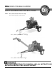
DR® ROAD-TOWABLE CHIPPER SAFETY & OPERATING INSTRUCTIONS Models: 18 HP, Road-Towable, Bottom Discharge 19 HP, Road-Towable, Top Discharge 18 HP, Road-Towable, Bottom Discharge 19 HP, Road-Towable, Top Discharge READ AND UNDERSTAND THIS MANUAL AND ALL INSTRUCTIONS BEFORE OPERATING THIS WOOD CHIPPER.
And congratulations on your purchase of a new DR ROAD-TOWABLE CHIPPER! We have done our utmost to ensure that your DR ROAD-TOWABLE CHIPPER will be one of the most troublefree and satisfying pieces of equipment you have ever owned. Please let us know of any questions you may have. We want to answer or correct them as quickly as possible. When you do call, please have your serial number and/or order number handy.
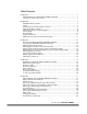
Table of Contents CHAPTER 1............................................................................................................................. 1 INTRODUCING THE DR ROAD-TOWABLE CHIPPER.................................................. 1 Conventions used in this manual ................................................................................... 1 CHAPTER 2.............................................................................................................................
CHAPTER 6........................................................................................................................... 47 TROUBLESHOOTING................................................................................................... 47 Troubleshooting Table................................................................................................... 47 CHAPTER 7...........................................................................................................................
CHAPTER 1 INTRODUCING THE DR ROAD-TOWABLE CHIPPER This manual will help you set up and safely operate your new DR ROAD-TOWABLE CHIPPER. Careful adherence to the safety and operating instructions in this manual will ensure many years of productive use. Please let us know of any questions you may have. We want to answer them as quickly as possible. When you do call, please have your serial number and/or order number handy.
2 DR® 18 and 19 HP ROAD-TOWABLE CHIPPER
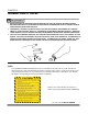
CHAPTER 2 GENERAL SAFETY RULES • • • READ THIS SAFETY & OPERATING MANUAL BEFORE YOU USE THE DR ROAD-TOWABLE CHIPPER. BECOME FAMILIAR WITH THE OPERATION AND SERVICE RECOMMENDATIONS TO ENSURE THE BEST PERFORMANCE FROM YOUR MACHINE. THOROUGHLY INSPECT THE AREA IN WHICH YOU WILL BE WORKING AND REMOVE ALL FOREIGN OBJECTS. LOOK FOR ROPE, WIRE, ETC., AND REMOVE THESE OBJECTS BEFORE CHIPPING. INSERTING THESE OBJECTS INTO THE CHIPPER HOPPER COULD DAMAGE THE MACHINE AND/OR CAUSE INJURY.
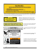
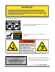
Before removing the Discharge Chute on the 19 HP Top Discharge model, ALWAYS turn OFF the engine, wait five (5) minutes to make certain the flywheel and all moving parts have come to a complete stop and cool and then disconnect the spark plug wires. (#091-0378) ALWAYS turn OFF the engine, wait five (5) minutes to make certain the flywheel and all moving parts have come to a complete stop and cool and then disconnect the spark plug wires before opening this access panel.
ALWAYS wear eye protection and know where the Discharge Chute and Deflector are pointing. Be aware of your surroundings. (#091-0379) To avoid injury, keep your hands and feet out of the Inlet and Discharge Chutes. (#091-0057) These label warns you of a hot surface, DO NOT touch. (#091-0384) NEVER operate the Chipper without the Discharge Chute properly secured in place. (#091-0444) CAUTION CLUTCH DAMAGE DUE TO ENGINE OVERLOAD CAN BE VERY COSTLY AND MAY NOT BE COVERED UNDER WARRANTY.
ALWAYS turn OFF the engine, wait five (5) minutes to make certain the flywheel and all moving parts have come to a complete stop and cool, and then disconnect the spark plug wires before servicing the machine. (#091-0381) WARNING: Check Oil Before Starting Engine Always check the engine oil before starting the DR CHIPPER. (#091-0256) This DR CHIPPER is road-towable at a maximum safe speed of 45 MPH; DO NOT exceed. (#091-0093) The DR ROAD-TOWABLE CHIPPER is made in the U.S.A.
Protecting Yourself and Those Around You THIS IS A HIGH-POWERED MACHINE, WITH MOVING PARTS OPERATING WITH HIGH ENERGY AT HIGH SPEEDS. THE MACHINE MUST BE OPERATED SAFELY. UNSAFE OPERATION CAN CREATE A NUMBER OF HAZARDS FOR YOU, AS WELL AS ANYONE ELSE IN THE NEARBY AREA. ALWAYS TAKE THE FOLLOWING PRECAUTIONS WHEN USING THIS MACHINE: • ALWAYS WEAR PROTECTIVE GOGGLES OR SAFETY GLASSES WITH SIDE SHIELDS WHILE CHIPPING TO PROTECT YOUR EYES FROM POSSIBLE THROWN DEBRIS.
Safety for Children and Pets TRAGIC ACCIDENTS CAN OCCUR IF THE OPERATOR IS NOT ALERT TO THE PRESENCE OF CHILDREN AND PETS. CHILDREN ARE OFTEN ATTRACTED TO THE MACHINE AND THE CHIPPING ACTIVITY. NEVER ASSUME THAT CHILDREN WILL REMAIN WHERE YOU LAST SAW THEM. ALWAYS FOLLOW THESE PRECAUTIONS: • • • KEEP CHILDREN AND PETS OUT OF THE WORKING AREA AND UNDER THE WATCHFUL CARE OF A RESPONSIBLE ADULT. BE ALERT AND TURN THE MACHINE OFF IF CHILDREN OR PETS ENTER THE WORK AREA.
Towing Safety • • • • BEFORE TOWING, BE CERTAIN THE DR ROAD-TOWABLE CHIPPER IS CORRECTLY AND SECURELY ATTACHED TO THE TOWING VEHICLE AND THE SAFETY CHAINS ARE IN PLACE. LEAVE SLACK IN THE CHAINS TO ALLOW FOR TURNING. NEVER ALLOW ANYONE TO RIDE ON THE DR ROAD-TOWABLE CHIPPER. NEVER TRANSPORT ANYTHING ON THE MACHINE. OBEY LOCAL, STATE, AND FEDERAL REGULATIONS WHEN YOU TOW THE CHIPPER ON PUBLIC ROADS AND HIGHWAYS.
General Safety THE CHIPPER MUST BE OPERATED SAFELY TO PREVENT OR MINIMIZE THE RISK OF DEATH OR SERIOUS INJURY. UNSAFE OPERATION CAN CREATE A NUMBER OF HAZARDS FOR YOU. ALWAYS TAKE THE FOLLOWING PRECAUTIONS WHEN OPERATING THIS CHIPPER: • • • • • • • • • • • • • • • 10 KEEP IN MIND THAT THE OPERATOR OR USER IS RESPONSIBLE FOR ACCIDENTS OR HAZARDS OCCURRING TO OTHER PEOPLE, THEIR PROPERTY, AND THEMSELVES. YOUR DR ROAD-TOWABLE CHIPPER IS A POWERFUL TOOL, NOT A PLAYTHING.
• • • • • • NEVER OVERLOAD OR ATTEMPT TO CHIP MATERIAL BEYOND THE MANUFACTURER’S RECOMMENDATION; SEE PAGE 27. PERSONAL INJURY OR DAMAGE TO THE MACHINE COULD RESULT. WHILE USING THE DR ROAD-TOWABLE CHIPPER, DON'T HURRY OR TAKE THINGS FOR GRANTED. WHEN IN DOUBT ABOUT THE EQUIPMENT OR YOUR SURROUNDINGS, STOP THE MACHINE AND TAKE THE TIME TO LOOK THINGS OVER. NEVER OPERATE THE MACHINE WHEN UNDER THE INFLUENCE OF ALCOHOL, DRUGS, OR MEDICATION. USE THE MACHINE ONLY IN DAYLIGHT.
12 DR® 18 and 19 HP ROAD-TOWABLE CHIPPER
CHAPTER 3 SETTING UP YOUR DR ROAD-TOWABLE CHIPPER This chapter outlines unpacking and a few simple steps you will need to follow to set up your new machine before you use it. If you have any questions at all, please feel free to contact our Customer Service Representatives at our toll free number: 1-800-DR-OWNER (376-9637).
Unpacking the DR ROAD-TOWABLE CHIPPER NOTE: Unpacking the DR ROAD-TOWABLE CHIPPER is a two-person job. We recommend you have an extra set of hands available before you begin as the 18 HP model weighs 385 lbs. and the 19 HP model weighs 470 lbs.
• • WEAR EYE PROTECTION WHEN CUTTING THE BANDING. THE BANDING MAY HAVE A LOT OF TENSION ON IT AND MAY SNAP AND CUT YOU. ALWAYS STAND TO ONE SIDE WHEN CUTTING THE BAND. STABILIZE THE SHIPPING CONTAINER ON CLEAN FLAT TERRAIN BEFORE ATTEMPTING TO UNPACK AND ASSEMBLE THE MACHINE. 1. Pry off the crate and cut any bands holding the machine to the pallet. Be careful when cutting the banding. 2.
Attaching the Hitch Arms and Hitch Assembly Tool Needed: • (2) 3/4" Wrench or Socket 1. Attach the two (2) Hitch Arms to the Trailer Frame using the two (2) Hitch Arm Mounting Plates and four (4) 1/2"-13 x 1-1/4" Bolts (Figure 2). DO NOT tighten the bolts at this time. 2. Attach the Trailer Hitch Assembly to the Hitch Arms with two (2) 1/2"- 13 x 3" Bolts and two (2) 1/2"- 13 Lock Nuts (Figure 2). Tighten all of the hardware. 3.
Attaching the Discharge Chute (19 HP Top Discharge model) Tool Needed: • (2) 1/2" Wrench or Socket 1. Loosen the two (2) 5/16"-18 x 4" Bolts on the Chipper Rear Side Panel (Figure 3) just enough so that the top L-shaped notches in the Mounting Plates on the Discharge Chute will slide onto the Bolt. You may have to slightly tap the Nut side of the Bolt to center it before the Discharge Chute can easily slide into place. 2.
Attaching the Swivel Top and Deflector (19 HP Top Discharge model) Tool Needed: • (2) 1/2" Wrench or Socket 1. Hold the Swivel Top (Figure 4) in place on the Discharge Chute and insert two (2) of the 5/16"-18 x 3/4" Carriage Bolts through two (2) 3/8" Flat Washers and then through both the top two (2) slots of the Swivel Base on the Discharge Chute, and the top two (2) holes on the Swivel Top. Securely tighten with two (2) 5/16"-18 Lock Nuts. 2.
Attaching the Wire Harness The wire harness supplied must be installed on the trailer of your new DR ROAD-TOWABLE CHIPPER before you can transport the machine on public roadways. Identify the “Road Side” and “Curb Side of the trailer from Figure 5 below. NOTE: There is an Access Hole in each Tail Light Mounting Bracket so the Wire Harness can be attached to each light. The Yellow/Brown wire in the Harness is for the Road Side light and Green/Brown wire is for the Curb Side light.
Connecting the Battery Cable We ship all DR ROAD-TOWABLE CHIPPERS with the negative terminal battery cable disconnected. This prevents the battery from discharging during shipment. Before using your DR ROAD-TOWABLE CHIPPER, you must connect the battery cable. Tool Needed: • (2) 5/16" Wrenches or Sockets Connect the negative cable to the negative terminal on the battery (Figure 6).
Adding Engine Oil and Gasoline • YOU MUST ADD OIL BEFORE STARTING THE ENGINE. THIS MACHINE IS SHIPPED WITHOUT OIL. TRACES OF OIL MAY BE IN THE RESERVOIR FROM FACTORY TESTING, BUT YOU MUST ADD OIL BEFORE STARTING THE ENGINE. FILL THE RESERVOIR SLOWLY CHECKING THE DIPSTICK FREQUENTLY TO AVOID OVERFILLING. • TO GET AN ACCURATE READING WHEN CHECKING THE OIL LEVEL: ⇒ THE MACHINE SHOULD BE ON A LEVEL SURFACE. ⇒ THE DIPSTICK SHOULD BE SCREWED DOWN ON BRIGGS & STRATTON ENGINES. Capacities Briggs & Stratton 18.
Gas Fill Gas Tank Oil Fill Briggs and Stratton 18 HP Engine Oil Fill Gas Fill Dip Stick Gas Tank Fuel Filter Kawasaki 19 HP Engine Figure 7 Check the Tire Pressure There should be 60 psi in each tire.
CHAPTER 4 OPERATING YOUR DR ROAD-TOWABLE CHIPPER This chapter covers the procedures for starting and stopping your new DR ROAD-TOWABLE CHIPPER and discusses basic operation features. • • • THIS CHIPPER IS DESIGNED FOR CHIPPING WOOD. NEVER USE THIS MACHINE FOR ANY OTHER PURPOSE AS IT COULD CAUSE SERIOUS INJURY. CONTACT WITH INTERNAL ROTATING PARTS WILL CAUSE SERIOUS PERSONAL INJURY. NEVER PUT HANDS, FACE, FEET, OR CLOTHING INTO CHIPPER HOPPER OR DISCHARGE OPENING OR NEAR THE DISCHARGE AREA AT ANY TIME.
Operation Notes • Visually check the Chipper Knife for damage each time you use the machine. NOTE: Check for shaft movement while starting the engine. If the shaft does not turn, clean out the Chipper as instructed on page 28. • At engine start-up, the engine of your DR CHIPPER operates under no load until approximately 1200-1400 RPM, at which speed the Centrifugal Clutch engages and begins driving the Rotor Assembly. • Proper Rotor speed is 2400-RPM +/- 200 RPM.
Processing Material • • • • • • ALWAYS WEAR PROTECTIVE GOGGLES OR SAFETY GLASSES WITH SIDE SHIELDS WHILE CHIPPING TO PROTECT YOUR EYES FROM POSSIBLE THROWN DEBRIS. AVOID WEARING LOOSE CLOTHING OR JEWELRY, WHICH MIGHT CATCH ON MOVING PARTS OR THE MATERIAL FED INTO THE CHIPPER HOPPER. WE RECOMMEND WEARING GLOVES WHILE CHIPPING. BE SURE YOUR GLOVES FIT PROPERLY AND DO NOT HAVE LOOSE CUFFS OR DRAWSTRINGS. WEAR SHOES WITH NON-SLIP TREADS WHEN USING YOUR CHIPPER.
Electric-Starting 1. Pull the Choke control (Figure 8 on page 23) out to the CHOKE position (leave in the RUN position if the engine is already warm). 2. Move the Throttle to the FAST or RUN position (Figure 8 on page 23). 3. Turn the Key Switch to ON (Figure 8 on page 23) then to the START position until the engine starts, then release. The key will snap back to the RUN position and the engine will continue to run. 4. As the engine warms up, slowly adjust the Choke to the Run position.
Using the Chipper Hopper The Chipper Hopper is mounted on the side of the machine and is designed to chip wood only. The revolving Chipper Knife mounted on a flywheel turns branches fed into the hopper into “chips”. The Chipper can chip branches and vines ranging in size up to 4-1/2" in diameter. Cut your materials into manageable lengths before feeding them into the Chipper Hopper.
To Free a Jammed Flywheel BEFORE PERFORMING ANY MAINTENANCE PROCEDURE OR INSPECTION, STOP THE ENGINE, WAIT FIVE (5) MINUTES TO ALLOW ALL MOVING PARTS TO COME TO A COMPLETE STOP AND COOL. DISCONNECT THE SPARK PLUG WIRES, KEEPING THEM AWAY FROM THE SPARK PLUGS. Tool Needed: (2) 1/2" Wrench or Socket Disassemble: 1. Disconnect the battery at the negative terminal (Figure 6 on page 20). 2.
Reassemble Bottom Discharge model: 1. Hold the Deflector (Figure 10 on page 28) in place at the Discharge opening of the Chipper. 2. Place a 5/16" Flat Washer on a 5/16"-18 x 4" Bolt and then slide the Bolt through both the top two (2) holes of the Chipper body and the Deflector. NOTE: Be certain that the Bolt attaching the Deflector to the Chipper passes through the pipe (tube) welded to the Scroll (Figure 10 on page 28). 3. Add a 5/16" Flat Washer to the end of the Bolt followed by a 5/16"-18 Lock Nut.
30 DR® 18 and 19 HP ROAD-TOWABLE CHIPPER
CHAPTER 5 MAINTAINING THE DR ROAD-TOWABLE CHIPPER This chapter covers regular maintenance procedures that will ensure the best performance and long life of your DR ROAD-TOWABLE CHIPPER. For engine maintenance, please refer to the Engine Owner’s Manual that came with your machine. Service intervals listed in the checklist below supercede those listed in the Engine Owner’s Manual.
Grease Fittings Your DR ROAD-TOWABLE CHIPPER was greased at the Factory. The operator needs to lubricate the Chipper Side and Drive Side Bearings periodically. BEFORE PERFORMING ANY MAINTENANCE PROCEDURE OR INSPECTION, STOP THE ENGINE, WAIT FIVE (5) MINUTES TO ALLOW ALL MOVING PARTS TO COME TO A COMPLETE STOP AND COOL. DISCONNECT THE SPARK PLUG WIRES, KEEPING THEM AWAY FROM THE SPARK PLUGS.
Removing and Replacing the Engine Oil and Filter BEFORE PERFORMING ANY MAINTENANCE PROCEDURE OR INSPECTION, STOP THE ENGINE, WAIT FIVE (5) MINUTES TO ALLOW ALL MOVING PARTS TO COME TO A COMPLETE STOP AND COOL. DISCONNECT THE SPARK PLUG WIRES, KEEPING THEM AWAY FROM THE SPARK PLUGS.
Oil Drain Valve Oil Drain Valve Oil Filter Oil Filter Briggs and Stratton 18 HP Engine Kawasaki 19 HP Engine Figure 12 34 DR® 18 and 19 HP ROAD-TOWABLE CHIPPER
Adjusting or Removing and Replacing the Drive Belts BEFORE PERFORMING ANY MAINTENANCE PROCEDURE OR INSPECTION, STOP THE ENGINE, WAIT FIVE (5) MINUTES TO ALLOW ALL MOVING PARTS TO COME TO A COMPLETE STOP AND COOL. DISCONNECT THE SPARK PLUG WIRES, KEEPING THEM AWAY FROM THE SPARK PLUGS. USE ONLY DR BELTS ON YOUR MACHINE. THE BELTS HAVE BEEN THOROUGHLY TESTED AND PROVEN FOR MANY HOURS OF USE.
e) Using a straightedge, align the Clutch and Drive Pulley as shown in Figure 15 by moving the Drive Pulley in or out on the Rotor Shaft (Figure 16 on page 37). Do not make the adjustment by moving the Clutch on the Engine Shaft. f) Remove the three (3) Bolts and reinsert them into the original Retaining Bolt holes. NOTE: Prior to retightening the Hub Retaining Bolts, move the Drive Pulley out approximately 1/8" from the straightedge to allow for compression of the Hub Bushing during the tightening process.
Bushing Saw Slot Drive Pulley Bushing Rotor Shaft Threaded Holes (3) Hub Retaining Bolt (3 places) Drive Pulley Hub Bolt Figure 16 CALL TOLL FREE 1-800-DR-OWNER 37
Removing and Replacing the Chipper Knife ROUTINELY CHECK THE CHIPPER KNIFE FOR SHARPNESS. USING A DULL KNIFE WILL DECREASE PERFORMANCE AND CAUSE EXCESSIVE VIBRATION THAT WILL CAUSE DAMAGE TO THE DR ROADTOWABLE CHIPPER ENGINE. BEFORE PERFORMING ANY MAINTENANCE PROCEDURE OR INSPECTION, STOP THE ENGINE, WAIT FIVE (5) MINUTES TO ALLOW ALL MOVING PARTS TO COME TO A COMPLETE STOP AND COOL. DISCONNECT THE SPARK PLUG WIRES, KEEPING THEM AWAY FROM THE SPARK PLUGS.
Tools Needed: • • • 5/16" Wrench 3/16" Allen wrench 1/2" socket and ratchet 1. Using a 5/16" Wrench, remove both Access Covers (Chipper and Drive Side) from the Chipper Box (Figure 1 on page 15). 2. Rotate the Chipper Disk using a stick until the three (3) countersunk Allen Screws and Lock Nuts attaching the Knife to the Flywheel are visible through the Access Openings. 3. Clean out the heads of the Allen Screws with an awl or sharp tool. 4. Insert a 3/16” Allen wrench into the head of a screw. 5.
Adjusting the Knife to Wear Plate Gap When you replace the Knife, check and set the clearance between the Knife and Wear Plate. Set this clearance or gap to 1/16" (Figure 19). If the gap between the Wear Plate and the Knife is not set correctly, you will have excessive vibration when chipping and the Knife will seem to be dull. The Wear Plate should have a square edge and be free of dents or gouges. The Wear Plate can be hand sharpened. Be careful not to overheat it during the sharpening process.
Removing and Replacing the Clutch BEFORE PERFORMING ANY MAINTENANCE PROCEDURE OR INSPECTION, STOP THE ENGINE, WAIT FIVE (5) MINUTES TO ALLOW ALL MOVING PARTS TO COME TO A COMPLETE STOP AND COOL. DISCONNECT THE SPARK PLUG WIRES, KEEPING THEM AWAY FROM THE SPARK PLUGS. The design of the Clutch on your machine is for rugged, dependable service, however, it is important to understand the limitations of a Clutch.
Installing a New Clutch Assembly If you have problems with the Clutch, we recommend replacing your Clutch as a complete assembly. Tools and Supplies Needed: • • • • (2) 1/2" Wrench 9/16" Socket with Extension (18 HP) 5/8" Socket with Extension (19 HP) Anti-seize compound 1. Remove the Belt Guard and loosen the Engine Bolts as outlined in Steps 1 and 2 on page 35. 2. After you have loosened the Engine Bolts, remove the Drive Belts and set them aside. 3.
Clutch Removal, Disassembly, and Re-Assembly If it is necessary to disassemble your Clutch, follow these steps. Tools and Supplies Needed: • • • • • 9/16" Socket with Extension (18 HP) 5/8" Socket with Extension (19 HP) Pliers, Retainer Ring Pliers (wrap the gripping surface in tape to avoid scratching the spring surface) Anti-seize compound 1. Perform steps 1 through 4 on the previous page to remove the Clutch. 2.
Battery Care Proper care can extend the life of a battery. Follow these recommendations to ensure your battery’s best performance and long life: • Do not allow the battery charge to get too low. If the machine is not used, charge the battery every 4 – 6 weeks. Operate the engine for at least 45 minutes to maintain proper battery charge. • • Store an unused battery in a dry area that does not freeze. • Do not continue to crank your engine when the battery charge is low.
End of Season and Storage • • • BEFORE PERFORMING ANY MAINTENANCE PROCEDURE OR INSPECTION, STOP THE ENGINE, WAIT FIVE (5) MINUTES TO ALLOW ALL MOVING PARTS TO COME TO A COMPLETE STOP AND COOL. DISCONNECT THE SPARK PLUG WIRES, KEEPING THEM AWAY FROM THE SPARK PLUGS. NEVER STORE THE DR ROAD-TOWABLE CHIPPER WITH FUEL IN THE FUEL TANK INSIDE A BUILDING WHERE IGNITION SOURCES ARE PRESENT, SUCH AS HOT WATER AND SPACE HEATERS, CLOTHES DRYERS AND THE LIKE.
46 DR® 18 and 19 HP ROAD-TOWABLE CHIPPER
CHAPTER 6 TROUBLESHOOTING Most problems are easy to fix. Consult the Troubleshooting Table below for common problems and their solutions. If you continue to experience problems, call Country Home Products, Inc. for support. Troubleshooting Table BEFORE PERFORMING ANY MAINTENANCE PROCEDURE OR INSPECTION, STOP THE ENGINE, WAIT FIVE (5) MINUTES TO ALLOW ALL MOVING PARTS TO COME TO A COMPLETE STOP AND COOL. DISCONNECT THE SPARK PLUG WIRES, KEEPING THEM AWAY FROM THE SPARK PLUGS.
BEFORE PERFORMING ANY MAINTENANCE PROCEDURE OR INSPECTION, STOP THE ENGINE, WAIT FIVE (5) MINUTES TO ALLOW ALL MOVING PARTS TO COME TO A COMPLETE STOP AND COOL. DISCONNECT THE SPARK PLUG WIRES, KEEPING THEM AWAY FROM THE SPARK PLUGS. SYMPTOM The engine lacks power or is not running smoothly. (Please refer to the Engine Owner’s Manual for enginespecific procedures.) POSSIBLE CAUSE ⇒ Check the Throttle Lever travel and adjustment.
BEFORE PERFORMING ANY MAINTENANCE PROCEDURE OR INSPECTION, STOP THE ENGINE, WAIT FIVE (5) MINUTES TO ALLOW ALL MOVING PARTS TO COME TO A COMPLETE STOP AND COOL. DISCONNECT THE SPARK PLUG WIRES, KEEPING THEM AWAY FROM THE SPARK PLUGS. SYMPTOM The machine has excessive vibration. POSSIBLE CAUSE ⇒ Check for a dull or damaged Knife; sharpen or replace the Knife. See page 38. ⇒ The Knife may not be properly seated on the flywheel. Loosen the Knife mounting screws, reset the Knife and tighten the screws.
CHAPTER 7 PARTS LISTS, SCHEMATIC DIAGRAMS AND WARRANTY Parts List - DR ROAD-TOWABLE CHIPPER Assembly - 18 HP, Bottom Discharge NOTE: Part numbers listed are available through Country Home Products, Inc.
Schematic - DR ROAD-TOWABLE CHIPPER Assembly - 18 HP, Bottom Discharge 060103 CALL TOLL FREE 1-800-DR-OWNER 51
Parts List - DR ROAD-TOWABLE CHIPPER Assembly - 19 HP, Top Discharge NOTE: Part numbers listed are available through Country Home Products, Inc.
Schematic - DR ROAD-TOWABLE CHIPPER Assembly - 19 HP, Top Discharge 060103 CALL TOLL FREE 1-800-DR-OWNER 53
Parts List - 19 HP Control Panel Assembly NOTE: Part numbers listed are available through Country Home Products, Inc.
Schematic - 19 HP Control Panel Assembly 060103 CALL TOLL FREE 1-800-DR-OWNER 55
Parts List - Basic Machine Assembly - 18 and 19 HP NOTE: Part numbers listed are available through Country Home Products, Inc.
Schematic - Basic Machine Assembly - 18 and 19 HP 060103 CALL TOLL FREE 1-800-DR-OWNER 57
Notes 58 DR® 18 and 19 HP ROAD-TOWABLE CHIPPER
DR® ROAD-TOWABLE CHIPPER 2-Year Limited Warranty Terms and Conditions The DR® ROAD-TOWABLE CHIPPER is warranted for two (2) years against defects in materials or workmanship when put to ordinary and normal consumer use; ninety (90) days for any other use. The engine manufacturer warrants the engine separately.
Daily Checklist for the DR ROAD-TOWABLE CHIPPER To help maintain your DR ROAD-TOWABLE CHIPPER for optimum performance, we recommend you follow this checklist each time you use your machine. [ ] OIL: With the machine on a level surface, check the engine oil level with the dipstick and add more if necessary (only add oil to the level indicated on the dipstick - DO NOT OVERFILL). Use SAE 30 high detergent motor oil. [ ] GAS: Fill the gas tank with clean, fresh, unleaded gasoline.