DR ALL-TERRAIN FIELD and BRUSH MOWER Safety & Operating Instructions Please read instructions before operating machine
And congratulations on your purchase of a new DR ALL-TERRAIN FIELD and BRUSH MOWER! We have done our utmost to ensure that your DR ALL-TERRAIN FIELD and BRUSH MOWER will be one of the most trouble-free and satisfying pieces of equipment you have ever owned. Please let us know of any questions or problems you may have. We want to answer or correct them as quickly as possible.
Table of Contents Chapter 1: Introducing the DR ALL-TERRAIN FIELD and BRUSH MOWER......1 About This Manual ......................................................................................................................... 1 Chapter 2: Safety Considerations..........................................................................3 Preparing to Use the DR ALL-TERRAIN FIELD and BRUSH MOWER ......................................... 3 Safety Information Labels.............................................
Chapter 6: Troubleshooting .................................................................................35 Troubleshooting Table...................................................................................................................35 Chapter 7: Parts Lists, Schematic Diagrams and Warranty ..............................40 Parts List — Handlebar Assembly.................................................................................................40 Schematic – Handlebar Assembly...........
Chapter 1: Introducing the DR ALL-TERRAIN FIELD and BRUSH MOWER This manual will help you set up and safely operate your new DR ALLTERRAIN FIELD and BRUSH MOWER. Careful adherence to the safety and operating instructions in this manual will ensure many years of productive use. Please let us know of any questions you may have. We want to answer them as quickly as possible. When you do call, please have your order number handy.
Conventions used in this manual WARNING! The exclamation point within an equilateral triangle alerts you to essential operating, safety, and maintenance (servicing) instructions. Important! This information is important in the proper use of your machine. Failure to follow this instruction could result in injury to you or damage to your mower. Tip: This is a helpful hint to guide you in getting the most out of your mower.
Chapter 2: Safety Considerations WARNING! This mowing machine is capable of amputating hands and feet and throwing objects. Failure to observe the following safety instructions could result in serious injury or death. Taking the time to read and observe all safety instructions will ensure many years of productive use from your DR ALL-TERRAIN FIELD and BRUSH MOWER and help you avoid injury. Please take a few moments to read the following guidelines for safely operating your new machine.
To avoid injury, keep your hands and feet away from the spinning blade. (#136491) Move the throttle to the CHOKE position to start the engine (to the RUN or IDLE position if the engine is already warm). (#164541) This label shows the proper routing of the drive belt. (#164371) This label reminds you about the importance of reading and understanding the Safety & Operating Instructions manual and of paying attention to the safety warnings.
WARNING! The items listed in this section will help you keep your DR ALLTERRAIN FIELD and BRUSH MOWER running smoothly and, most importantly, prevent injury to yourself or others. Please review them carefully before starting your machine. Protecting Yourself ■ ■ ■ ■ ■ ■ Always wear the protective goggles or safety glasses with side shields while mowing to protect your eyes from possible thrown objects. Wear shoes with non-slip treads when using your DR ALL-TERRAIN FIELD and BRUSH MOWER.
■ ■ ■ ■ ■ ■ ■ ■ ■ ALWAYS OPERATE THE MOWER FROM BEHIND. Never pass or stand on the discharge (right) side or in front of machine when the engine is running. Do not pull the mower backwards unless absolutely necessary. Look down and behind before and while moving backwards. Do not, under any conditions, remove, bend, cut, fit, weld, or otherwise alter standard parts on the DR ALL-TERRAIN FIELD and BRUSH MOWER. This includes all shields and guards.
Safety for Children Tragic accidents can occur if the operator is not alert to the presence of children. Children are often attracted to the mower and the mowing activity. Never assume that children will remain where you last saw them. Keep children out of the mowing area and under the watchful care of a responsible adult. Be alert and turn the mower OFF if children enter the work area. Before and while moving backwards, look behind and down for small children. Never allow children to operate the mower.
A Note to All Users Under California law, and the laws of some other states, you are not permitted to operate an internal combustion engine using hydrocarbon fuels without an engine spark arrester. This also applies to operation on US Forest Lands. All DR ALL-TERRAIN FIELD and BRUSH MOWERS shipped to California and Washington State are provided with spark arresters.
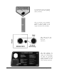
Chapter 3: Setting Up Your DR ALL-TERRAIN FIELD and BRUSH MOWER This chapter outlines a few simple steps you will need to follow to set up your new machine before you use it. It may be helpful to familiarize yourself with the controls and features on your mower by reviewing the picture in the next section before beginning the steps outlined in this chapter.
DR ALL-TERRAIN FIELD and BRUSH MOWER Controls and Features Note: The model shown in Figure 1 may look slightly different from your machine.
Unpacking the Mower NOTE: Unpacking the DR ALL-TERRAIN FIELD and BRUSH MOWER is a twoperson job. We recommend you have an extra set of hands available before you begin. Tools & Supplies Needed: Screwdriver Hammer Knife Gloves WARNING! The banding may have a lot of tension on it and may snap, cutting you when cut. Always stand to one side when cutting the band. 1. Stand to one side and cut the banding. 2. Remove the top of the carton.
To Install the Brush Deck WARNING! Before performing any maintenance procedure, stop the engine and disconnect the spark plug wire(s). 1. Remove the black belt guard by unscrewing the black knob, lifting the cover and pulling up and back to remove it. The belt is shipped wrapped around the pulley. 2. Slide the power unit shaft into the brush deck and install collar and pin (Figure 2). 3. Install the belt on the pulley and clutch (Figure 3) and route the belt per the label on the spindle housing (Figure 4).
Connecting the Battery Wire (Electric-Starting Models Only) We ship all electric-starting mowers with the negative terminal battery wire disconnected. This prevents the battery from discharging during shipment. Before using your mower, you must connect the battery wire. Tools Needed: (2) 5/16 wrenches or sockets 1. Connect the negative wire to the negative terminal on the battery (Figure 6).
Adding Oil and Gasoline WARNING! You must add oil before starting the engine. This machine is shipped without oil. Traces of oil may be in the reservoir from factory testing, but you must add oil before starting the engine. Fill the reservoir slowly checking the dipstick frequently to avoid overfilling. Important! To get an accurate reading when checking the oil level: ⇒ The machine should be on a level surface. ⇒ The dipstick should be screwed down on Briggs & Stratton engines.
Chapter 4: Operating Your DR ALL-TERRAIN FIELD and BRUSH MOWER This chapter covers the procedures for starting and stopping your new DR ALLTERRAIN FIELD and BRUSH MOWER and discusses basic operation features. You may find it helpful to review the DR ALL-TERRAIN FIELD and BRUSH MOWER Controls and Features picture (Figure 1) on page 10 before reading this chapter.
Checking and adjusting clutch engagement: 1. Start your machine in the normal manner. 2. With the operator presence lever depressed, shift into low gear. 3. Increase the engine rpm but do not squeeze the clutch lever. The machine should not move when the clutch lever is not squeezed WARNING! If your machine “creeps” during this test, your clutch needs adjustment. Consult Chapter 5, page 29 of your Safety & Operating Instructions manual and make all necessary corrections before using.
Engaging the Wheel Drive The DR ALL-TERRAIN FIELD and BRUSH MOWER has a four-speed forward transmission and single-speed reverse. Forward speeds range from 1.1 mph in first gear to 4.5 mph in fourth gear. Use the lower gears for mowing in thick, woody vegetation and the higher gears for wide-open areas and lighter vegetation, or as "travel gears." Reverse is ideal for maneuvering in tight spots. Note: Always release the wheel clutch lever (see mower picture, Figure 1, on page 10) when shifting gears. 1.
Stopping the Engine 1. Disengage the blade by pulling the Blade Control Lever (see Figure 1, on page 10) back to the DISENGAGED position. 2. Move the Shift Lever to the N (Neutral) position. 3. Move the Throttle Control to the IDLE position. 4. Turn the Key to the OFF position and remove it for safety. 5. Set the Parking Brake. Note: If your machine is equipped with a fuel shut-off valve, close it when transporting or storing the mower.
Slopes WARNING! When operating the DR ALL-TERRAIN FIELD and BRUSH MOWER over uneven terrain or slopes, use EXTREME CAUTION not to tip the machine over. 1. Do not use the DR ALL-TERRAIN MOWER on slopes greater than 20 degrees. Doing so could result in serious injury or damage to your machine. 2. To avoid freewheeling, shift into a lower gear before going down a slope. Do not shift while on a slope. 3.
Cutting Brush & Saplings 1. When cutting woody material, small saplings, etc., allow the machine to ride up and over material slowly. Adjust your forward speed to varying conditions (Figure 9). 2. After cutting brush, etc., you may want to mow over it again to remove any remaining branches. It works best to mow from the trunk end toward the top as brush lies on the ground. Reverse Figure 9 1. Be very careful of your footing when operating the machine in reverse. Know what's behind you and take your time.
Chapter 5: Maintaining the DR ALL-TERRAIN FIELD and BRUSH MOWER This chapter covers regular maintenance procedures that will ensure the best performance and long life of your machine. For engine maintenance, please refer to the engine owner’s manual that came with your mower. Service intervals listed in the checklist below supercede those listed in the engine owner’s manual. WARNING! Some of the following procedures require access to the underside of the machine.
Battery Care (For Electric-Starting Models Only) Proper care can extend the life of a battery. Follow these recommendations to ensure your battery’s best performance and long life: ■ ■ ■ ■ Do not allow the battery charge to get too low. If the machine is not used, the battery should be charged every 4 – 6 weeks. Engine must be operated for at least 45 minutes to maintain proper battery charge. Store an unused battery in a dry area that does not freeze. Do not charge an already charged battery.
Lubrication Your DR ALL-TERRAIN FIELD and BRUSH MOWER was greased at the Factory. The operator needs to lubricate the Wheel Clutch Cable, Brake Cable, Belt Idler Arm and the Drive Chain, periodically. Tools & Supplies Needed: ■ Flexible hose grease gun ■ Lithium grease ■ 1/2" wrench or socket (chain cover) ■ FLUID FILM® or comparable lubricant WARNING! Before performing any maintenance procedure, stop the engine and disconnect the spark plug wire(s).
Grease Fittings 1. There is one grease fitting below the black belt guard that needs maintenance (Figure 11): ■ The belt idler arm should have 1-2 pumps of grease every 25 operating hours. Belt Idler Arm Grease Fitting Note: Over greasing will cause grease to leak out of the seals onto the mower drive belt. Unless instructed Figure 11 otherwise, pump only until you feel slight resistance (1-2 pumps). 2.
Removing and Replacing the Belts WARNING! Before performing any maintenance procedure, stop the engine and disconnect the spark plug wire(s). Important! Use only DR belts on your machine. They have been thoroughly tested and proven for many hours of use. To Replace the Blade Belt 1. Remove the black belt guard by unscrewing the black knob, lifting the cover, and pulling up and back to remove it. Belt Tension Lever 2. Release the belt tension lever (Figure 14). 3.
To Replace the Drive Belt WARNING! Before performing any maintenance procedure, stop the engine and disconnect the spark plug wire(s). Tools Needed: ■ 7/16" socket ■ 1/2" wrench ■ 9/16" wrench ■ Gloves 1. Drain the gas and oil. 2. Remove the blade belt following the instructions as outlined in the previous page. 3. Remove the pin and collar (Figure 16), and then pull the power unit away from the deck. 4. Tilt the power unit forward onto the attachment pin.
5. Remove the nuts on the clutch bracket and the clutch drive spring (Figure 17). 6. Remove the spring (Figure 18). Remove Belt Guides Spring Clutch Bracket Spring Remove Nuts Figure 18 Figure 17 7. Lift and swing the clutch bracket out of the way (Figure 18). 8. Remove the three belt guides (Figure 18). 9. Loosen the belt retainer bolts on the outside of the frame (one on each side) and slide the retainer back (Figure 19). 10. Remove the belt. 11. To mount the new belt, reverse the above procedure.
Removing and Replacing the Blade WARNING! Before performing any maintenance procedure, stop the engine and disconnect the spark plug wire(s). Tools Needed: ■ 15/16" wrench or socket ■ Air wrench if available ■ Wear gloves ■ 2 x 4 to brace the blade 1. Block the blade with a piece of wood between the blade and the skid on the chute side of the deck (Figure 20). 2. Remove the blade lock nut (righthand, regular thread) and washer.
Adjusting the Wheel Clutch WARNING! Before performing any maintenance procedure, stop the engine and disconnect the spark plug wire(s). Note: When properly adjusted, tension on the wheel clutch lever should increase when the lever is about parallel to (almost touching) the handlebar grip. Tools Needed: ■ (2) 1/2" wrenches 1. Find the wheel clutch adjustment on the clutch bracket on the underside of the machine (Figure 21). 2.
Removing and Replacing the Drive Chain WARNING! Before performing any maintenance procedure, stop the engine and disconnect the spark plug wire(s). Tools Needed: ■ 1/2" wrench or socket (chain cover) ■ Flat-head screwdriver ■ Needle Nose Pliers 1. Remove the Chain Cover (Figure 22). 2. Remove the Tensioner Spring (Figure 23). 3. Remove the Master Chain Link (Figure 24).
Adjusting the Blade Engagement Cable WARNING! Before performing any maintenance procedure, stop the engine and disconnect the spark plug wire(s). Note: If the blade won't cut, or seems to slip in heavy material, check the blade engagement cable. Tool Needed: ■ 1/2" open-end wrench On the right handlebar there is a black bracket for adjusting the blade engagement cable (Figure 25). To tighten the cable, turn the center portion of the adjuster counter clockwise.
Removing the Wheels WARNING! Before performing any maintenance procedure, stop the engine and disconnect the spark plug wire(s). Tool Needed: Remove Nuts ■ 3/4" socket with extension 1. Block the machine so the wheel to be removed is off the ground. 2. Remove the three nuts and slide the wheel off (Figure 26). Figure 26 Adjusting the Parking Brake WARNING! Before performing any maintenance procedure, stop the engine and disconnect the spark plug wire(s).
Transmission The transmission is maintenance-free and does not need additional lubrication. Removing or Changing the Deck WARNING! Before performing any maintenance procedure, stop the engine and disconnect the spark plug wire(s). 1. Remove the black belt guard by unscrewing the black knob, lifting the cover and pulling up and back to remove it. Belt Tension Lever 2. Release the belt tension lever (Figure 28). 3. Remove the belt from the pulley (Figure 29). 4.
End of Season & Storage WARNING! Before performing any maintenance procedure, stop the engine and disconnect the spark plug wire(s). Note: Please refer to the engine owner's manual for engine-specific procedures. ■ ■ ■ ■ ■ ■ ■ ■ ■ Change the oil (and oil filter, if applicable). For winter use, use SAE 5 – 30 HD. Remove the spark plug(s) and pour about 1 ounce of motor oil into the cylinder hole. Replace the plug(s) and pull the recoil starter rope until you feel strong resistance.
Chapter 6: Troubleshooting Most problems are easy to fix. Consult the troubleshooting table for common problems and their solutions. If you continue to experience problems call Country Home Products, Inc. for support. Troubleshooting Table WARNING! Before performing any maintenance procedure, stop the engine and disconnect the spark plug wire(s). SYMPTOM Recoil will not pull out or is difficult to pull. POSSIBLE CAUSE ⇒ Check that the blade lever is in the disengaged position.
SYMPTOM The engine won’t start using electric-start. POSSIBLE CAUSE ⇒ Have you checked all the items under the section called Electric Starting on page 16? If not, do so now. (Please refer to the engine owner’s manual for enginespecific procedures.) ⇒ Check the wire connections—especially the ground connection, the large green wire coming from the battery, where it connects to the engine. ⇒ There is a fuse in the wiring harness. Check the fuse and replace if needed.
SYMPTOM The engine lacks power or is not running smoothly. (Please refer to the engine owner’s manual for enginespecific procedures.) Engine smokes. Machine is hard to get into reverse. The belt frays or rolls over the pulley. POSSIBLE CAUSE ⇒ Check the throttle travel and adjustment. ⇒ Is the air filter clean? If it’s dirty, change it following the procedure in the engine manufacturer’s owner’s manual. ⇒ Is the spark plug(s) clean? If it’s fouled or cracked, change it.
38 SYMPTOM The cut material is not being properly discharged out of the right side of the machine. POSSIBLE CAUSE ⇒ The discharge may be blocked. Disengage the blade, turn off the engine, set the brake and disconnect the spark plug wire(s), then check for debris. Heavier growth gets hung up under the machine and does not discharge. ⇒ Try removing the baffle under the front of the mowing deck. Blade vibrates when engaged. The blade is not cutting or is loose.
DR ALL-TERRAIN FIELD and BRUSH MOWER Safety & Operating Instructions 39
Chapter 7: Parts Lists, Schematic Diagrams and Warranty Parts List — Handlebar Assembly Note: Part numbers listed are available through Country Home Products, Inc.
Schematic – Handlebar Assembly DR ALL-TERRAIN FIELD and BRUSH MOWER Safety & Operating Instructions 41
Parts List — Power Unit Assembly Note: Part numbers listed are available through Country Home Products, Inc. Ref# Part# 01 150261 02 160171 160181 160191 160881 03 150411 04 150291 05 150011 06 150531 07 150591 08 111141 09 151001 10 160331 11 150171 12a 164771 12b 164781 13 150101 14 150481 15 16 17 18 19 20 21 22 23 24 25 150181 150211 111871 150241 112391 150201 150611 151111 108501 150021 150501 26 27 28 150061 150461 112481 42 Description Frame, Main Engine, 11.
Schematic – Power Unit Assembly DR ALL-TERRAIN FIELD and BRUSH MOWER Safety & Operating Instructions 43
Parts List — Brush Deck Assembly Note: Part numbers listed are available through Country Home Products, Inc. Ref# Part# 01 164561 160621 02 157261 03 160091 04 150891 05 151331 06 07 08 09 10 11 12 13 14 15 44 164371 164451 164401 150831 150711 150641 151141 160511 160611 100481 160891 101771 Description Brush Deck, 26 inch Brush Deck, 30 Inch Spindle Support Assembly Shaft, Spindle Bearing, Ball, .787" Bore Key, Parallel, Round Ends, 1/4" x 3/16" x 7/8" Label, Belt Routing Pulley, V, 8.
Schematic – Brush Deck Assembly DR ALL-TERRAIN FIELD and BRUSH MOWER Safety & Operating Instructions 45
Parts List — Differential/Axle Assembly Note: Part numbers listed are available through Country Home Products, Inc. Ref# 01 02 03 04 05 06 07 08 09 10 46 Part# 150251 150621 151721 150191 165221 110761 123211 168241 168261 151971 Description Differential, Limited Slip Wheel & Tire, 18" x 6.50" – 8", Terrain, 5 Lug Wheel & Tire, 18" x 6.
Schematic – Differential/Axle Assembly DR ALL-TERRAIN FIELD and BRUSH MOWER Safety & Operating Instructions 47
Notes 48 DR ALL-TERRAIN FIELD and BRUSH MOWER Safety & Operating Instructions
DR® POWER EQUIPMENT DR ALL-TERRIAN FIELD and BRUSH MOWER 1-Year Limited Warranty Terms and Conditions The DR ALL-TERRAIN FIELD and BRUSH MOWER is warranted for one (1) year against defects in materials or workmanship when put to ordinary and normal consumer use; ninety (90) days for any other use. The engine manufacturer warrants the engine separately.
Daily Checklist for the DR FIELD and BRUSH MOWER To help maintain your DR ALL-TERRIAN FIELD and BRUSH MOWER for optimum performance, we recommend you follow this checklist each time you use your machine. [ ] OIL: With the machine on a level surface, check the engine oil level with the dipstick and add more if necessary (only add oil to the level indicated on the dipstick - DO NOT OVERFILL). Use SAE 30 high detergent motor oil. [ ] GAS: Fill the gas tank with clean, fresh, unleaded gasoline.