DR® LEAF & LAWN VACUUM OPTIONAL ACCESSORIES SAFETY & OPERATING INSTRUCTIONS READ AND UNDERSTAND THIS MANUAL AND ALL INSTRUCTIONS BEFORE USING YOUR NEW ACCESSORY
And congratulations on your purchase of a new DR LEAF and LAWN VACUUM Optional Accessory! We have done our utmost to ensure that your DR LEAF and LAWN VACUUM Optional Accessory will be one of the most trouble-free and satisfying pieces of equipment you have ever owned. Please let us know of any questions or problems you may have. We want to answer or correct them as quickly as possible. When you do call, please have your order number handy.
Table of Contents CHAPTER 1............................................................................................................................. 1 INTRODUCING THE DR OPTIONAL ACCESSORIES ................................................... 1 Conventions used in this manual ................................................................................... 1 CHAPTER 2.............................................................................................................................
CHAPTER 1 INTRODUCING THE DR OPTIONAL ACCESSORIES This manual will help you set up and safely operate your new DR LEAF and LAWN VACUUM Optional Accessory. Careful adherence to the safety and operating instructions in this manual will ensure many years of productive use. Please let us know of any questions you may have. We want to answer them as quickly as possible. When you do call, please have your order number handy.
CHAPTER 2 GENERAL SAFETY RULES • • • • READ THIS SAFETY AND OPERATING MANUAL BEFORE YOU USE THE DR LEAF AND LAWN VACUUM OPTIONAL ACCESSORY. ALSO, REVIEW THE SAFETY AND OPERATING MANUAL FOR YOUR SYSTEM. INSPECT THE AREA WHERE YOU WILL BE WORKING. THE SITE MUST BE FREE OF POTENTIALLY HAZARDOUS OBSTACLES (E.G., STONES, GLASS AND METAL OBJECTS SUCH AS CANS). TURN OFF YOUR LAWN TRACTOR AND DR LEAF AND LAWN VACUUM ENGINES BEFORE DISCONNECTING ANY HOSES TO INSTALL OR REMOVE YOUR ACCESSORY.
CHAPTER 3 DR LEAF AND LAWN VACUUM OPTIONAL ACCESSORIES This chapter outlines a few simple steps you will need to follow to set up and use your new Optional Accessories that are available for your DR LEAF and LAWN VACUUM. If you have any questions at all, please feel free to contact our Customer Service Representatives at our toll free number: 1-800-DR-OWNER (376-9637). Connecting and Using the Optional Hand Vacuum Attachment (Kit No.
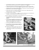
1. The Handle Ring is shipped in a position suitable for packaging with the Ring Clamp Bolt only partially tightened. Rotate the Handle Ring upward but do not tighten at this time (Figure 1). 2. Locate the two (2) Bolts protruding from the Nozzle and align the two (2) holes at the end of the Handle Bar and add a Lock Nut on each Bolt (Figure 1). Tighten the Lock Nuts using the 1/2" wrench. 3. Thread the Support Tie through the Eyebolt and wrap it around the Hose.
Tip: When vacuuming leaves off mulched areas, hold the nozzle just above the leaves and lower it slowly to determine the height that will pickup the leaves and not the mulch. Tip: When vacuuming leaves in an area with loose brush, twigs and branches; step on them to hold them down so as not to ingest them into the vacuum nozzle (Figure 5). They may clog or puncture a hole in the vacuum hose. Once you have cleared the area of leaves, pick up, and chip the twigs and sticks that you uncovered during vacuuming.
Installing and Using the Optional Bagging Accessory The DR LEAF and LAWN VACUUM can utilize nine (9) Bagger Box Inserts in the Commercial model (6 for the Premier) that fit into the Collector Box for ease of bagging leaves and grass (Figure 6). For proper bagging operation, you MUST install all boxes in the Collector Box. BEFORE PERFORMING THIS PROCEDURE, STOP THE BLOWER ENGINE AND DISCONNECT THE SPARK PLUG WIRE. Commercial model: (Kit No. 18796) 1.
Premier model: (Kit No. 18795) Outer Panel Pre-formed Edge Inner Panel Slide Side Spacer Figure 8 Pre-formed Notch Shown with Top removed Spacer Tube Side Spacer Front Perpendicular surface facing out Rear Figure 9 7 DR® LEAF and LAWN VACUUM Optional Accessories 1. Remove the Rear Panel of the Collector Box by releasing the six (6) Flexible Latches and lift it off the pins protruding on the top corners. 2.
Installing and Using the Optional Mulch-Discharge Attachment (Kit No. 18791) In addition to vacuuming and chipping with the DR LEAF and LAWN VACUUM, the system also allows you to discharge material for mulch in a specific area. This attachment is used in conjunction with the hand vacuum attachment. The vacuum attachment hose is used to vacuum the material out of the Collector Box. BEFORE PERFORMING THIS PROCEDURE, STOP THE BLOWER ENGINE AND DISCONNECT THE SPARK PLUG WIRE. 1.
DO NOT STAND OR ALLOW PEOPLE OR PETS NEAR THE DISCHARGE OPENING. MATERIAL IS EXITING THE HOSE AT A HIGH RATE AND COULD CAUSE INJURY.
Installing the Optional Universal Lawn Deck Adapter (Kit No. 21168) The design of the DR Universal Lawn Deck Adapter is adaptable to a variety of Mower Decks as found on the various makes of tractors and mowing machines. The intension of the information provided here is to show a typical method for obtaining measurements and determining shapes and contours for proper fitting of the unit to your machine. Your particular machine may require slightly different or additional operations to obtain the best fit.
1. Before proceeding with the installation, familiarize yourself with the Parts, and the illustrations of the Universal Lawn Deck Adapter as shown in Figure 13. 2. Thoroughly clean the exposed area of your Mower Deck so that it may be easily marked. 3. Remove the Hinge Pin from your Mower Deck Mounting Bracket (Figure 14) and remove the Discharge Chute, Springs, and related parts from your Mower Deck. Do not remove the Mounting Bracket. (See Reference Line instruction below).
Mower Deck Mounting Bracket Installing Your Deck Adapter Reference Line The following outlines the typical steps necessary for installing a Universal Lawn Deck Adapter to your Lawn Tractor. The procedure requires patience, around two (2) hours to complete, and skill working with a Jig Saw to match contours. 1. Establish a Reference Line. Straight Edge Figure 15 shows the typical location of a Reference Line on your Mower Deck.
2. Make the vertical (side) Template. a) Place the Straight Edge against the edge of the Mounting Bracket and clamp it in place (Figure 16 on page 12). b) Draw a line across the top of your Mower Deck. Using the Square, extend the line down the sides at each end (Figure 17 on page 12). Extending the Square from the Straight Edge to the contours can make more Reference Line points. NOTE: Before using the Template Wire, it is helpful to straighten it.
i) Place the Universal Deck Adapter on its side (Figure 21) on the Template Board. Trace the outline and cut the board to the outline. Make note of the Front and Bottom on the Template Board. j) Draw a line 1/2” from the bottom edge of the Template Board (Figure 22). This represents the bottom of the Discharge Chute or Baseline. Tracing the Contour Figure 21 k) Using HEIGHT A. from Step c) on page 12, draw a horizontal line across the Template at the A Height above the baseline.
3. Make the horizontal (bottom) Template. a) Using the vertical Reference Lines (Figure 17 on page 12), place the Template Board beneath the Discharge Chute with the leading edge aligned to the Reference Lines (Figure 26) and centered right to left. b) Clamp the Template Board in place and trace the outer edge of the Discharge Chute on to the Template Board (Figure 26). Figure 26 c) Cut the outline from the Template Board.
4. Cut the Universal Deck Adapter. a) Drill a Pilot Hole (Figure 29) near the Contour Line. b) Insert the Blade of the Jig Saw and carefully cut along the contours until the piece is free from the Universal Deck Adapter (Figure 30). Clean the burrs from the cut line. c) The corners of the Universal Deck Adapter opening where the side and bottom contours meet may require minor adjustments for a final fit. Hold the Universal Deck Adapter in place on your Mower Deck and note any problem areas.
Large Height Distance 1. Internal Mount a) Slot the Universal Deck Adapter (Figure 32) to receive the Hinge Plate Arms. You can do this by drilling 1/4” holes at the top and bottom of the slot locations and inserting the Saw Blade into the hole to remove the remaining material or cutting directly from the edge of the contour.
6. Hinge Assembly The Hinge hardware supplied with your Universal Deck Adapter accommodates a variety of hinge widths as supplied by various manufacturers. Proper assembly is important. During use, the assembled hinge will look as shown in (Figure 35). The force of the forward movement of the tractor holds the Mower Deck Mounting Bracket toward the front of the assembly while in motion. Push Nut Push Nut Mower Deck Mounting Bracket Front Figure 35 7.
CHAPTER 4 PARTS LISTS AND SCHEMATIC DIAGRAMS Parts List - Hand Vacuum Hose Assembly (Kit No. 18789) NOTE: Part numbers listed are available through Country Home Products. Ref# Part# Description 01 02 03 04 05 06 07 08 09 10 11 12 13 14 15 16 Nozzle Hose, Vacuum, 14 FT. Clamp, Hose, 6" Handle Grip, 1" Bolt, HCS, 5/16"-18 x 1" Washer, Flat, 5/16" USS Nut, Nylon Lock, 5/16"-18 Bolt, Eye, 5/16"-18 x 3" Nut, 5/16"-18, ZP, GR2 Tie, Cable, 15" Coupling Keeper, Draw Latch, 4" Rivet, Blind, Alum., 3/16" Dia. x .
Schematic Diagram - Hand Vacuum Hose Assembly CALL TOLL FREE 1-800-DR-OWNER 20
Parts List - Bagging Accessory (Kit # 18796 Commercial, # 18795 Premier Model) NOTE: Part numbers listed are available through Country Home Products.
Parts List - Mulch-Discharge Hose (Kit No. 18791) NOTE: Part numbers listed are available through Country Home Products. Ref# Part# Description 01 02 Hose, Discharge, 17 FT Adapter, Male/Female, 6" Coupling, Hose, Male, 6" Latch, Draw Clamp, Hose, 6" Rivet, Blind, Alum., 3/16" Dia. x .312" Rivet, Blind, Alum., 3/16" Dia. x .
Parts List - Universal Lawn Deck Adapter (Kit No. 18794) NOTE: Part numbers listed are available through Country Home Products.
Schematic Diagram - Universal Lawn Deck Adapter CALL TOLL FREE 1-800-DR-OWNER 24
NOTES 25 DR® LEAF and LAWN VACUUM Optional Accessories
NOTES CALL TOLL FREE 1-800-DR-OWNER 26
Daily Checklist for the DR LEAF and LAWN VACUUM To help maintain your DR LEAF and LAWN VACUUM for optimum performance, we recommend you follow this checklist each time you use your machine. [ ] OIL: With the machine on a level surface, remove the oil fill cap and check the oil level. Fill the reservoir according to the dipstick with SAE 30 HD motor oil. See page 25 of the Safety & Operating Instructions for your DR Leaf and Lawn Vacuum. [ ] GAS: Fill the gas tank with fresh, unleaded gasoline.