Selection and Operation A Shure Educational Publication Selection and Operation of Wireless Microphone Systems
A B L E O F C O N T E N T S Introduction . . . . . . . . . . . . . . . . . . . . . . . . 4 PART ONE WIRELESS MICROPHONE SYSTEMS: HOW THEY WORK CHAPTER 1 BASIC RADIO PRINCIPLES . . . . . . . . . . 5 Radio Wave Transmission . . . . . . . . . . . . . 5 Radio Wave Modulation . . . . . . . . . . . . . . 7 BASIC RADIO SYSTEMS . . . . . . . . . . . . 8 System Description . . . . . . . . . . . . . . . . . . 8 Input Sources . . . . . . . . . . . . . . . . . . . . . . 8 Transmitter: General Description . . . .
of Wireless Microphone Systems Selection and Operation I N T R O D U C T I O N The many uses of wireless microphone systems can span applications from live entertainment to earth-orbit communications. It can include devices from a single "Mr. Microphone" to a 60 channel theme park system. It can evoke visions of freedom in prospective users and memories of ancient disaster in veteran sound engineers. In all its forms, wireless has become a fact of life for people who design and use audio systems.
Part One: Wireless Microphone Systems: How They Work H A P T E R 1 Basic Radio Principles RADIO WAVE TRANSMISSION of Wireless Microphone Systems Radio refers to a class of time-varying electromagnetic fields created by varying voltages and/or currents in certain physical sources. These sources may be "artificial," such as electrical power and electronic circuits, or "natural," such as the atmosphere (lightning) and stars (sunspots).
of Wireless Microphone Systems Selection and Operation C H A P T E R 1 Basic Radio Principles The speed of radio waves (through a vacuum) is equal to approximately 3 x 10⁸ meter/second, or about 186,000 miles/ second. This is also known as the "speed of light," since light is just one part of the radio spectrum. The wave equation states that the frequency of a radio wave, multiplied by its wavelength always equals the speed of light.
H A P T E R 1 Basic Radio Principles RADIO WAVE MODULATION This discussion of radio transmission has so far dealt only with the basic radio wave. It is also necessary to consider how information is carried by these waves. Audio "information" is transmitted by sound waves which consist of air pressure variations over a large range of amplitudes and frequencies. This combination of varying amplitudes and varying frequencies creates a highly complex sound field.
of Wireless Microphone Systems Selection and Operation 8 C H A P T E R 2 Basic Radio Systems The output of the receiver is typically monitored through headphones or loudspeakers. It may feed a portable The function of a radio or "wireless" system is to send audio or video recorder. This is the configuration of information in the form of a radio signal.
H A P T E R 2 Basic Radio Systems to clothing or belt, or may be placed in a pocket or pouch. In theater and some other applications they may be concealed underneath clothing. Input is made from the source to the bodypack via a cable, which may be permanently attached or detachable at a connector. This connector may allow a variety of input sources to be used with one transmitter.
of Wireless Microphone Systems Selection and Operation C H A P T E R 2 Basic Radio Systems Handheld transmitter controls are generally limited called pre-emphasis, which is designed to minimize the to a power switch, a mute switch, and gain adjustment. apparent level of high frequency noise (hiss) that is Again, tuneable models include some provision for unavoidably added during the transmission. The "emphasis" frequency selection.
H A P T E R 2 Basic Radio Systems Figure 2-5: compander (2:1, fixed rate) TRANSMITTER: RADIO CIRCUITRY After processing, the audio signal is sent to a voltagecontrolled oscillator (VCO). This is the section that actually converts the audio signal to a radio signal by the technique called frequency modulation (FM). The (relatively) low frequency audio signal controls a high frequency oscillator to produce a radio signal whose frequency "modulates" or varies in direct proportion to the audio signal.
of Wireless Microphone Systems Selection and Operation C H A P T E R 2 Basic Radio Systems A few tuneable transmitters use multiple crystals to obtain multiple frequencies. However, the base frequency of the VCO for most tuneable systems is adjustable by a technique known as frequency synthesis. A control circuit called a phase-locked-loop (PLL) is used to calibrate the transmitter frequency to a reference "clock" frequency through an adjustable frequency divider.
H A P T E R 2 Basic Radio Systems Figure 2-10: general receiver block diagram frequency and still yield the same difference frequency when combined in the mixer. When the LO frequency is lower than the received frequency the design is called "low-side injection." When it is above it is called "high-side injection." The sum and difference signals are then sent to a series of filter stages that are all tuned to the frequency of the difference signal.
of Wireless Microphone Systems Selection and Operation C H A P T E R 2 Basic Radio Systems only of frequency variations of the original input signal. This effectively eliminates the (high-frequency) carrier frequency leaving only the low-frequency modulation information (the original audio signal). In a quadrature FM detector the IF signal passes through a circuit which introduces a 90 degree phase shift relative to the original IF signal.
H A P T E R 2 Basic Radio Systems RECEIVER:ANTENNA CONFIGURATION un-muted squelch threshold RF Level RF signal and noise muted Radio Frquency RF Noise Audio Characteristic AF Noise Level muted unmuted Noise Squelch Threshold Audio Characteristic non-diversity (single antenna) diversity (two antennas) of Wireless Microphone Systems Figure 2-14: threshold squelch Fixed receivers are offered in two basic external configurations: diversity and non-diversity.
of Wireless Microphone Systems Selection and Operation C H A P T E R 2 Basic Radio Systems RECEIVER: DIVERSITY TECHNIQUES Figure 2-18: multipath These multiple paths result in differing levels, arrival times and phase relationships between the radio waves. The net received signal strength at any location is the sum of the direct and reflected waves. These waves can reinforce or interfere with each other depending on their relative amplitude and phase.
H A P T E R 2 Basic Radio Systems Figure 2-20: passive antenna combining Figure 2-22: antenna switching Figure 2-23: receiver switching Figure 2-24: receiver combining of Wireless Microphone Systems Figure 2-21: antenna phase switching The next variation, "antenna switching diversity," again consists of a single receiver with two antennas. The receiver includes circuitry that selects the antenna with the better signal according to an evaluation of the radio signal.
of Wireless Microphone Systems Selection and Operation C H A P T E R 2 Basic Radio Systems output will usually consist of a mix of the two audio sections. In the case of loss of reception at one antenna, the output is chosen from the other section. Excellent dropout protection is obtained with no possibility of switching noise since the diversity circuit is essentially an intelligent panpot, not a switch. (See Figure 2-24.) Signal-to-noise is improved by up to 3 dB.
H A P T E R 2 Basic Radio Systems Figure 2-26: 1/4 wave and 1/2 wave antennas UHF range receiver or antenna distribution system. In addition, it is resistant to the effects of electrical noise that might otherwise be picked up at the interface. When antenna size is an issue, such as for portable receivers, the previously mentioned 1/4 wave rubber duckie is an option. UHF designs can use 1/4 wave rubber duckies because of the shorter wavelengths.
of Wireless Microphone Systems Selection and Operation C H A P T E R 2 Basic Radio Systems varies in a logarithmic progression so that at any given frequency one or more dipoles are active while the others are functioning as reflecting or directing elements, depending on their size and location relative to the active element(s). The longer the boom and the greater the number of elements the greater is the bandwidth and the directivity. Helical antennas are highly directional and also broadband.
H A P T E R 2 Basic Radio Systems Figure 2-31: passive antenna distribution Figure 2-32a: active antenna distribution (one level) LARGE ROOM/ MULTI-ROOM APPLICATIONS Sometimes it is desired to use a single wireless transmitter throughout a very large space or in multiple rooms. It is difficult to get reliable reception from transmitters in distant rooms or in extremely large rooms, especially if there are many obstructions or strong RF interference.
of Wireless Microphone Systems Selection and Operation C H A P T E R 3 Wireless System Operation FREQUENCY BANDS FOR WIRELESS SYSTEMS Existing wireless microphone systems transmit and receive on a specific radio frequency, called the operating frequency. Individual radio frequencies are found in frequency "bands" which are specific ranges of frequencies. Use of radio frequencies in the United States is regulated by the FCC (Federal Communication Commission).
H A P T E R 3 Wireless System Operation Finally, these frequencies are not generally legal outside of the US and Canada. The larger part of the high-band VHF region is 174-216 MHz. This band is designated by the FCC for use by broadcasters and by commercial film/video producers ("Part 74"). The primary users of this band are VHF television channels 7-13. Once again, high quality audio is possible within legal deviation limits (+15 kHz).
THE UHF BAND The low-band UHF range of frequencies may be considered as two overlapping bands: low (450-536 MHz) and high (470-806). The primary users of these bands are business services such as land mobile radio and pagers (450-536 MHz) and UHF television channels 14-69 (470806 MHz). As in the high-band VHF region, unused television channels are allotted for wireless microphone system use by broadcasters and video/film producers.
H A P T E R 3 Wireless System Operation SYSTEM COMPATIBILITY OPERATING FREQUENCY INTERACTIONS: INTERMODULATION A single wireless microphone system can theoretically be used on any open operating frequency. When a second system is added it must be on a different operating frequency in order to be used at the same time as the first. This limitation arises from the nature of radio receivers: they cannot properly demodulate more than one signal on the same frequency.
of Wireless Microphone Systems Selection and Operation C H A P T E R 3 Wireless System Operation operating frequency. This further restricts available frequency choices as the number of simultaneous systems increases. It should be apparent from this discussion that the prediction of potential compatibility problems due to IM products is best left to computer programs.
H A P T E R 3 Wireless System Operation received signal by an amount equal to the intermediate frequency (IF). Specifically, the operating frequency is above the local oscillator frequency by an interval equal to the IF. When these two frequencies are applied to the mixer section (a non-linear circuit) one of the output frequencies of the mixer is this difference frequency (the IF), which is the tuned frequency of the subsequent IF stage filters. of Wireless Microphone Systems 10.
of Wireless Microphone Systems Selection and Operation C H A P T E R 3 Wireless System Operation multipliers. However, both types of transmitters can produce other spurious emissions due to power regulating circuitry, parasitic oscillations, carrier harmonics, etc. These emissions can all be controlled through careful design.
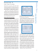
H A P T E R 3 Wireless System Operation country. As the distribution of Figure 3-12: major analog and digital TV channels in Chicago and Milwaukee vacant channels changes from city to city it is almost inevitable that a "touring" system will experience interference from a television station in some location. For example, Chicago has active high-band VHF TV channels 7, 9, and 11.
of Wireless Microphone Systems Selection and Operation C H A P T E R 3 Wireless System Operation DTV VS. WIRELESS SYSTEMS In the United States, the Federal Communications Commission (FCC) is currently supervising the transition of broadcast television from its traditional analog format to an all-digital format (DTV). In the process, the commission is also mandated to increase efficient use of TV spectrum and to increase the amount of spectrum available for public safety and other wireless services.
H A P T E R 3 Wireless System Operation BROADCAST RADIO OTHER RADIO SERVICES Direct pickup of 2-way radio, pagers, business band, ham-radio etc. is rare. However, since some of these sources can be quite strong locally there is the possibility of interference due to intermodulation or if the source appears as an image frequency. For example, operating a walkie-talkie near a wireless receiver can cause noise, distortion or apparent loss of range.
of Wireless Microphone Systems Selection and Operation C H A P T E R 3 Wireless System Operation SPREAD SPECTRUM TRANSMISSION A transmission technique that may have application to wireless microphone systems is known as "spread spectrum." The object of this technique is to improve performance by reducing interference effects and increasing efficiency of band utilization.
H A P T E R 3 Wireless System Operation DIGITAL WIRELESS SYSTEMS As other links in the audio chain have been converted to the digital domain it is of interest to look at the impact of digital technology on wireless transmission systems. Digital techniques can be applied to professional wireless in several ways, each offering potential benefits.
of Wireless Microphone Systems Selection and Operation 34 C H A P T E R 3 Wireless System Operation width than wireless microphones. Even so, bandwidth limitations necessitate the use of companders to achieve acceptable dynamic range in most high quality analog wireless systems. The bandwidth required for a high fidelity digital wireless system depends on the amount of digital information transmitted and the transmission rate.
H A P T E R 3 Wireless System Operation OPERATION OF WIRELESS SYSTEMS OUTSIDE OF THE U.S. specifications may differ from one band to another and may further differ from one type of user to another within the same band. For this reason, it is not possible to select a specific frequency or even frequency band that is (legally) useable in all parts of the world.
of Wireless Microphone Systems Selection and Operation Part Two: Wireless Microphone Systems: How To Make Them Work 36 C H A P T E R 4 Wireless System Selection and Setup SYSTEM SELECTION The proper selection of a wireless microphone system consists of several steps based on the intended application and on the capabilities and limitations of the equipment required for that application.
H A P T E R Selection and Operation C 4 CRYSTAL-CONTROLLED VS. FREQUENCY SYNTHESIS SYSTEM SETUP: TRANSMITTER Transmitter setup first requires optimizing the sourceto-transmitter interface. Sources include dynamic and condenser microphones, electronic musical instruments and general audio sources such as mixer outputs, playback devices, etc. The output signal of each of these sources is characterized by its level, impedance and configuration (balanced or unbalanced).
of Wireless Microphone Systems Selection and Operation C H A P T E R 4 required by the microphone (usually between 11 and 52 volts DC). If less than the minimum is available, the condenser microphone performance may be compromised with less headroom or more distortion. This is not a concern with dynamic microphones (which do not require power) or with condenser microphones powered by an internal battery. The bodypack transmitter presents the greatest range of possible interfaces.
H A P T E R 4 ✓OK NO receiver that is not equipped with compander circuitry. For tuneable transmitters, make sure that the transmitter is set to the same frequency as the receiver. The last step in transmitter setup is placement. Placement of a handheld or plug-on system is essentially the same as for a wired microphone of the same type. The unit may be mounted on a stand, boom or fishpole with an appropriate stand adapter, or it may be handheld.
of Wireless Microphone Systems Selection and Operation 40 C H A P T E R 4 Audio Interface Here we will discuss the sound system interface. Remember that the basic function of a wireless microphone system is to replace the connecting cable between the source and the sound system. In the typical case, the output of the wireless receiver will resemble the output of the original source both electrically and physically.
H A P T E R 4 The threshold type squelch adjustment procedure is: 1) 2) 3) 6) 7) 8) 9) 10) If noise squelch is used, no adjustment is normally necessary. Noise squelch mutes the receiver based on the signal-to-noise quality of the audio signal. The receiver will generally not produce noise in the absence of the transmitter signal. Setting the squelch above the default position will force the receiver to mute for mildly noisy signals, which will reduce the effective range somewhat.
of Wireless Microphone Systems Selection and Operation 42 C H A P T E R 4 SYSTEM SETUP: RECEIVER ANTENNAS Setup of receiver antennas involves first the antenna-toreceiver interface and then antenna placement. The simplest case is a receiver with the antenna(s) permanently attached. The antenna is typically a quarter-wave telescoping or possibly "rubber ducky" type.
H A P T E R 4 SYSTEM SETUP: BATTERIES SYSTEM CHECKOUT AND OPERATION Good practice with any wireless microphone system calls for a checkout of the system ahead of performance time. As suggested in the squelch adjustment section this should be done with all associated production equipment also on. This may reveal potential problems that are not apparent in a wireless-system-only test. of Wireless Microphone Systems Always use fresh batteries of the correct type in the transmitter and/or receiver.
of Wireless Microphone Systems Selection and Operation C H A P T E R 4 It should be noted in Step 3 (on pg. 43) that certain combinations of active transmitters and receivers might indicate pickup of an individual transmitter by more than one receiver. However, in Step 7 (on pg. 43), when all transmitters are active, each should be picked up by just its intended receiver.
H A P T E R 4 TROUBLESHOOTING WIRELESS MICROPHONE SYSTEMS TROUBLESHOOTING GUIDE Conditions: TX on, RCV on, single system Symptom No AF signal and no RF signal TX - RCV Distance any Possible cause Action low TX battery voltage replace battery No AF signal and no RF signal any No AF signal and no RF signal average TX and RCV tuned to different frequencies multipath dropout retune one or both units No AF signal and no RF signal long out of range use diversity RCV or reposition TX and/or RCV m
of Wireless Microphone Systems Selection and Operation 46 C H A P T E R 5 Application Notes Following are some suggestions on wireless microphone system selection and use for some specific applications. Each section gives typical choices and setup for microphones, transmitters and receivers as well as a few operating tips. PRESENTERS The most common wireless choice for presentations is a lavaliere/bodypack system, which allows hands-free use by a single speaking voice.
H A P T E R 5 Application Notes the polarity of the guitar amp is of no consequence. VOCALISTS The usual choice for vocalists is a handheld wireless microphone system for close pickup of the singing voice. It consists of a suitable vocal microphone element attached to a handheld transmitter used with a fixed receiver. The microphone/transmitter may be handheld or mounted on a microphone stand.
of Wireless Microphone Systems Selection and Operation 48 C H A P T E R 5 Application Notes AEROBIC/DANCE INSTRUCTION Aerobic and dance applications most often require bodypack wireless microphone systems to allow handsfree use by the instructor. The microphone is most often a headworn type, with a unidirectional element. This will give the best results for feedback control and overall sound quality.
H A P T E R 5 Application Notes WORSHIP Worship services may include presenter, vocalist and instrument applications. While wireless vocal and instrument use is essentially the same as outlined in the preceding sections, the presenter function may be somewhat different. Microphone, transmitter and receiver selection are as before but placement of the components may require extra consideration.
of Wireless Microphone Systems Selection and Operation 50 C H A P T E R 5 Application Notes FILM/VIDEOGRAPHY Film and videography applications usually call for lavaliere/ bodypack wireless microphone systems to minimize the visibility of the microphone. Handheld transmitters may also be used when visual appearance is not anissue. However, the receivers may be either fixed or portable. A common choice is a camera-mounted receiver used with a camcorder.
H A P T E R 5 Application Notes POINT-TO-POINT WIRELESS Introduction Often it is desirable (or even mandatory) to send an audio signal from one fixed location to another fixed location without wires. This is termed "point-to-point" wireless. In some cases this may involve a single transmit location and multiple receive locations, referred to as "point-to-multi-point" wireless.
of Wireless Microphone Systems Selection and Operation C H A P T E R 5 Application Notes Figure 5-1: point-to-point using a wireless microphone system Figure 5-2: point-to-point using an IEM system (with directional antennas for maximum range) Using wireless in-ear monitors for point-to-point A wireless in-ear monitor system (IEM) can also be used as a point-to-point system with only one modification at the receiver.
H A P T E R 5 Application Notes Antennas Maximum range of point-to-point wireless Summary The practical range for most of these systems in pointto-point applications is comparable to their published range in normal usage. For standard wireless systems this ranges from about 150 ft. to 800 ft. depending on various conditions. Directional antennas may boost these ranges by 50%. Good line of sight and the normal precautions for frequency selection are assumed. The maximum range system employs IEM devices.
of Wireless Microphone Systems Selection and Operation 54 C O N C L U S I O N It should be apparent from this presentation that wireless microphone systems are a technology that encompasses a very wide range of principles and applications. Today’s equipment has progressed to the point that excellent results can be achieved with minimal input from the casual user.
E F E R E N C E I N F O R M A T I O N Appendix A CALCULATION OF INTERMODULATION PRODUCTS The simplest IM products that can occur between any two operating frequencies (f1 and f2) are the sum of the two frequencies and the difference between the two frequencies: f1 + f2 (sum) f1 - f2 (difference) These IM products are sufficiently far away from the original frequencies that they will generally not cause problems to a third wireless microphone system in the original frequency band.
of Wireless Microphone Systems Selection and Operation R E F E R E N C E I N F O R M A T I O N Appendix A For determining compatibility of three frequencies (200 MHz, 195 MHz and 187 MHz in this example) the significant combinations become: Three-Transmitter Intermodulation Calculation Product Order Frequency f1 (original frequency) 1 200 f2 (original frequency) 1 195 f3 (original frequency) 1 187 f1 + f2 - f3 f1 - f2 + f3 f2 + f3 - f3 3 3 3 208 192 182 (2 x f1) - f2 (2 x f2) - f1 (2 x f1) - f3 (2
E F E R E N C E I N F O R M A T I O N Appendix B US TELEVISION CHANNELS (Analog Components) Channel Band Chroma Audio VHF Low Band 2 54-60 3 60-66 4 66-72 5 76-82 6 82-88 55.25 61.25 67.25 77.25 83.25 58.83 64.83 70.83 80.83 86.83 59.75 65.75 71.75 81.75 87.75 VHF High Band 7 174-180 8 180-186 9 186-192 10 192-198 11 198-204 12 204-210 13 210-216 175.25 181.25 187.25 193.25 199.25 205.25 211.25 178.83 184.83 190.83 196.83 202.83 208.83 214.83 179.75 185.75 191.75 197.75 203.75 209.75 215.
of Wireless Microphone Systems Selection and Operation R E F E R E N C E I N F O R M A T I O N Glossary Absorption the weakening of radio wave strength by losses in various materials Compressor a circuit which reduces the dynamic range of a signal by a fixed ratio, typically 2:1 in a compander system AF De-emphasis a fixed equalization which typically rolls off high frequencies in the second step of a two-step noise reduction process audio frequencies, typically 20-20,000 Hz.
E F E R E N C E I N F O R M A T I O N Glossary Field a distribution of energy in space, ie.
of Wireless Microphone Systems Selection and Operation R E F E R E N C E I N F O R M A T I O N Glossary Narrow band an FM signal in which the deviation is much less than the modulating frequency Sensitivity measure of a receiver’s ability to respond to weak radio signals Noise undesirable random audio or radio energy Shadow blocking of radio waves by reflective or absorptive (lossy) objects Operating frequency the final output frequency of a transmitter or the tuned frequency of a receiver Oscilla
E F E R E N C E I N F O R M A T I O N Illustrations Included In This Booklet of Wireless Microphone Systems Selection and Operation R 61
of Wireless Microphone Systems Selection and Operation R E F E R E N C E I N F O R M A T I O N Suggested Reading Suggested readings for more information on radio technology: • • • • • Solid State Radio Engineering, H. Krauss, C. Bostian, F. Raab (J. Wiley & Sons, 1980) Introduction to Communication Systems, F. Stremler (Addison-Wesley, 1982) Antenna Theory and Design, W. Stutzman, G. Thiele (J. Wiley & Sons, 1981) Frequency Synthesizers, V. Manassewitsch (J.
Additional Shure Publications Available: These guides are available free of charge. To request your complimentary copies, call one of the phone numbers listed below.