LAN Industrial Router ICR-2701 USER MANUAL
ICR-2701 c 2023 Advantech Czech s.r.o. No part of this publication may be reproduced or transmitted in any form or by any means, electronic or mechanical, including photography, recording, or any information storage and retrieval system without written consent. Information in this manual is subject to change without notice, and does not represent a commitment on the part of Advantech. Advantech Czech s.r.o.
ICR-2701 Used symbols Danger – Information regarding user safety or potential damage to the router. Attention – Problems that can arise in specific situations. Information, notice – Useful tips or information of special interest. Advantech Czech s.r.o., Sokolska 71, 562 04 Usti nad Orlici, Czech Republic Document No. MAN-0069-EN, revision from February 8, 2023. Released in the Czech Republic.
ICR-2701 Contents 1 Product Overview 1.1 1.2 1.3 1.4 1.5 1.6 1.7 1.8 2 Product Introduction . . . . . Hardware Overview . . . . . Order Codes . . . . . . . . . Package Contents . . . . . . Product Dimensions . . . . . Mounting Recommendations DIN Rail Mounting . . . . . . Product Label . . . . . . . . . . . . . . . . . . . . . . . . . . . . . . . . . . . . . . . . . . . . . . . . . . . . . . . . . . . . . . . . . . . . . . . . . . . . . . . . . . . . . . . . . . . . . . . . . . . . . . . . .
ICR-2701 List of Figures 1 1 2 3 4 5 6 7 8 9 10 11 12 13 Hardware Overview of the Router . . . . . Metal Box – Top and Front View . . . . . . Metal Box – Bottom, Side and Back View Plastic Box – Top and Front View . . . . . Plastic Box – Bottom, Side and Back View Position of the DIN Rail Clip . . . . . . . . Removing Router from the DIN Rail . . . . Label Example . . . . . . . . . . . . . . . Ethernet Connector Pinout . . . . . . . . . Connection of Power Supply . . . . . . .
ICR-2701 List of Tables 1 2 3 4 1 2 3 4 5 6 7 8 Hardware Overview of the Router . . . . . Order Codes Overview . . . . . . . . . . . Contents of Package . . . . . . . . . . . . Other Accessories . . . . . . . . . . . . . Ethernet Connector Pinout Description . . Power Supply Pinout . . . . . . . . . . . . USB Connector Pinout . . . . . . . . . . . LED Status Indication . . . . . . . . . . . Basic Parameters . . . . . . . . . . . . . . Standards and Regulations . . . . . . . .
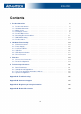
ICR-2701 1. Product Overview 1.1 Product Introduction Industrial router ICR-2701 is LAN Router & Edge Computing Gateway focused on the global market. The router, which may have a metal or plastic box, is equipped with two independently configurable Ethernet ports, with one USB 2.0 host interface and with LEDs for status indication. The router supports the Low Power Mode and hardware watchdog, which monitors the router status and performs an automatic restart if required.
ICR-2701 1.2 Hardware Overview The router case preview is shown in Figure 1. A short description of hardware parts of the router is listed in Table 1, including the links to the chapters with a detailed description. For a router in a plastic box, the description of the components is similar. Figure 1: Hardware Overview of the Router # Item/Caption Type Description 1 LED - Status LED indication; see Chapter 2.5. 2 USB USB-A USB-A type socket connector; see Chapter 2.4.
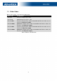
ICR-2701 1.3 Order Codes Order codes overview is shown in the table below.
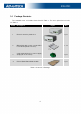
ICR-2701 1.4 Package Contents The standard router set includes items listed in Table 3: For other optional accessories, see Table 4.
ICR-2701 Table 4 lists items that may be included as accessories or can be ordered separately. See Chapter 1.3 for more information. Figure Description Ethernet cross cable of length 1.5 m. It can be ordered separately under BB-KD-ETH part number. Wall mount power supply, 12V/1A with EU plug.It can be ordered separately under BB-RPS-v2-EU part number. Wall mount power supply, 12V/1A with UK plug.It can be ordered separately under BB-RPS-v2-UK part number. Wall mount power supply, 12V/1A with US plug.
ICR-2701 1.5 Product Dimensions For the dimensions of the product in metal and plastic boxes see the figures below. Note that all sizes are measured in millimeters.
ICR-2701 Figure 2: Metal Box – Bottom, Side and Back View 8
ICR-2701 Variant with Plastic Box Figure 3: Plastic Box – Top and Front View 9
ICR-2701 Figure 4: Plastic Box – Bottom, Side and Back View 10
ICR-2701 1.6 Mounting Recommendations The router can be placed: • on a flat surface, • on a DIN rail EN 60715 with the metal DIN rail clip (see Chapter 1.7) For most applications with a built-in router within a switchboard, it is possible to recognize two kinds of environments: • A non-public, industry environment of low voltage with high interference, • a public environment of low voltage and without high interference.
ICR-2701 1.7 DIN Rail Mounting The DIN rail clip is suitable for a DIN rail according to EN 60715 standard only. There are four possible positions of the clip as shown in Figure 5. The DIN rail clip is the same for the metal and plastic router box. It just differs by the screws used. When mounting the DIN rail clip, tighten the screws with max. torque of 0.4 Nm.
ICR-2701 1.8 Product Label An example of the product label, with all the information printed on it, is in the figure below.
ICR-2701 2. Hardware Functionality See Chapter 1.2 for the product hardware overwiew. Table 1 lists a short description of the hardware, including the links to the chapters with a detailed description. 2.1 Ethernet Interfaces The panel socket of RJ45 is used for Ethernet interface. The pinout of the socket is shown in Figure 8 and described in Table 1.
ICR-2701 2.2 Power Supply The pins of power supply are physically connected to the 6-pin terminal block panel socket located on the left panel. The connection of power supply is shown in Figure 9 and described in Table 2.
ICR-2701 2.3 Low Power Mode In applications requiring low power consumption (such as solar power - not 7/24 mode) is strictly recommended to use LPM mode prior to powering down the entire router. LPM (Low Power Mode) is a router mode where the router is in sleep mode with minimal power consumption; see Chapter 4.1 for the LPM consumption. The router can be woken up from this mode after a predetermined period of time.
ICR-2701 USB Socket Pinouts USB socket pinouts is described in Figure 11 and Table 3. Figure 11: USB Connector Pinout Signal mark Description 1 +5 V Positive pole of 5 V DC supply voltage, 0.5 A 2 USB data - USB data signal – negative pole Input/Output 3 USB data + USB data signal – positive pole Input/Output 4 GND Negative pole of DC supply voltage Pin Data flow direction Table 3: USB Connector Pinout 2.
ICR-2701 2.6 Reset Functions Consider creating a router configuration backup before performing the router’s factory reset. The RST button can be used in three different scenarios: • Reset: Hold the RST button for less than 4 seconds; the router will reboot, applying its customized configuration. The router reset can be initiated by clicking the Reboot menu item in the router web GUI.
ICR-2701 3. First Use 3.1 Accessories Connection Before putting the router into operation, it is necessary to connect all the components required to run your applications; see Chapter 1.2 for the hardware overview. 3.2 Router Configuration Initial router configuration can be made via a web browser on your PC. Here you can perform router monitoring, configuration, and administration. Connect the power supply to the router, see Chapter 2.2, and the router will boot up.
ICR-2701 Figure 13: Router’s Web Interface A detailed description of the router settings in the web interface can be found in the configuration manual [1] of the router.
ICR-2701 4. Technical Specifications 4.1 Basic Parameters Router parameters Temperature range Operating Storage -40 ◦ C to +75 ◦ C -40 ◦ C to +85 ◦ C Humidity Operating Storage 5 to 95 % relative humidity non condensing 5 to 95 % relative humidity non condensing Altitude Operating 2000 m / 70 kPa Degree of protection IP30 Supply voltage 9 to 48 V DC Battery for RTC CR1225 Consumption Idle Average Maximum LPM mode 1.4 W 1.4 W 5.
ICR-2701 4.2 Standards and Regulations The router complies with the following standards and regulations: Standards and regulations EMC EN 61000-4-2, EN 61000-4-3, EN 61000-4-4, EN 61000-4-5, EN 61000-4-6, EN 61000-4-11, EN 61000-6-2, EN 61000-6-3, EN 55032 Safety IEC 62368-1, IEEE 802.
ICR-2701 4.
ICR-2701 4.4 System Configuration The main parametes of the system are listed in Table 8. Other technical parameters CPU architecture ARM926EJ-S CPU frequency 600 MHz CPU power 4,72 DMIPS/MHz Flash memory 4 MB of NOR 4 096 MB of eMMC • 838 MB for Router Apps • 512 MB for customer data RAM size 128 MB Watchdog HW Watchdog RTC Battery Backup RTC TPM1 Trusted Platform Module (TPM) 2.0 Table 8: System Configuration 1 Not assembled by default, for a dedicated customer order only.
ICR-2701 Appendix A: Troubleshooting If you cannot connect to the router from your PC, your network card may be configured in such a way that it is not possible to connect to the router. Take one or more of the following steps in order to solve the problem: • Make sure your PC’s network card is configured to obtain the IP address form the DHCP server (by default the DHCP server is running in the router). • Connect the router to the PC via Switch.
ICR-2701 ✍ L2TP or IPSec isn’t establishing. • Check the "System Log" page for error messages. ✍ IPSec tunnel establishes but the communication does not run. • Probably there are bad routing rules defined in the connected devices, or the default gateway. ✍ Serial communication is not working. • Verify that the router model supports serial communications. Also verify the serial communication settings.
ICR-2701 Appendix B: Customer Support Customer Support for Europe Advantech Czech s.r.o. Sokolska 71 562 04, Usti nad Orlici, Czech Republic Phone: Fax: E-mail: Web: +353 91 792444 +353 91 792445 iiotcustomerservice@advantech.eu www.advantech.com Customer Support for NAM Advantech B+B SmartWorx 707 Dayton Road Ottawa, IL 61350 USA Phone: Fax: E-mail: Web: +1-800-346-3119 (Monday – Friday, 7 a.m. to 5:30 p.m. CST) +1-815-433-5109 support@advantech-bb.com www.advantech-bb.
ICR-2701 Appendix C: Regulatory & Safety Information Safety Notices Please, observe the following instructions: • The router must be used in compliance with all applicable international and national laws and in compliance with any special restrictions regulating the utilization of the router in prescribed applications and environments. • To prevent possible injury and damage to appliances and to ensure compliance with all relevant provisions, use only the original accessories.
ICR-2701 Product Disposal Instructions The WEEE (Waste Electrical and Electronic Equipment: 2012/19/EU) directive was introduced to ensure that electrical/electronic products are recycled using the best available recovery techniques to minimize the environmental impact. This product contains high quality materials and components which can be recycled. At the end of it’s life this pro- duct MUST NOT be mixed with other commercial waste for disposal. The device contains a battery.
ICR-2701 Appendix D: Related Documents [1] Configuration Manual for v2i Platform [EP] Product-related documents and applications can be obtained on Engineering Portal at https://icr.advantech.cz/download address.
ICR-2701 We, Advantech Czech s.r.o., declare that the radio equipment narrated in this user’s manual complies with Directive 2014/53/EU (WiFi version) and with the essential requirements and other relevant provisions of Directives 2014/30/EU and 2014/35/EU (non-WiFi version). We, Advantech Czech s.r.o., declare that the radio equipment narrated in this user’s manual complies with Radio Equipment Regulations 2017 (S.I. 2017 No. 1206) and with the Electromagnetic Compatibility Regulations 2016 (S.I.