
Tus neeg siv phau ntawv

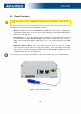
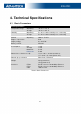
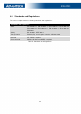


Table Of Contents

ICR-2701
USB Socket Pinouts
USB socket pinouts is described in Figure
11 and Table 3.
Figure 11: USB Connector Pinout
Pin
Signal mark Description Data flow direction
1
+5 V Positive pole of 5 V DC supply voltage, 0.5 A
2
USB data - USB data signal – negative pole Input/Output
3
USB data + USB data signal – positive pole Input/Output
4
GND Negative pole of DC supply voltage
Table 3: USB Connector Pinout
2.5 LED Status Indication
There are LED indicators on the front panel of the router to provide router status informa-
tion. Moreover, ETH connector, has two additional LEDs providing information about the port
status.
Caption Color S tate Description
PWR Green
Green
Green
On
Blinking
Fast blinking
The router is booting up.
The router booted up and is ready.
The router firmware is being updated.
ETH0
ETH1
Green
Green
On
Off
Selected 100 Mbps bit rate
Selected 10 Mbps bit rate
ETH0
ETH1
Orange
Orange
Orange
On
Blinking
Off
The network cable is connected.
Data transmission
The network cable is not connected.
Table 4: LED Status Indication
17