User Manual POC-621 Series (DC-/ AC-in model) 21" Computer
Instructions for the User This document combines text and illustrations, and provides a comprehensive system overview. The information is presented as a sequential steps of actions, enabling the user to learn how to use the device directly. The text provides explanations and instructs the user step-by-step in the practical use of the product, with short, clear instructions in an easy-to-follow sequence.
4. 5. If one of the following situations arises, get the equipment checked by service personnel: The power cord or plug is damaged. Liquid has penetrated into the equipment. The equipment has been exposed to moisture. The equipment does not work well, or you cannot get it to work according to the user's manual. The equipment has been dropped and damaged. The equipment has obvious signs of breakage. Disconnect this equipment from any AC outlet before cleaning. Use a damp cloth.
Caution! The battery charging indicator is not Included in this device. It will be added to the end system assembly and be shown in the end system. 9. Improper installation of VESA mounting can result in serious personal injury! VESA mount installation should be conducted by professional technician, please contact the service technician or your retailer if you need this service. The detail operating procedure specified on Appendix A. 10. CLASSIFICATION: 1). Class I internal powered 2). No applied part 3).
15. Accessory equipment connected to the analog and digital interfaces must be in compliance with the respective nationally harmonized IEC standards (i.e. IEC 60950 for data processing equipment, IEC 60065 for video equipment, IEC 61010-1 for laboratory equipment, and IEC 60601-1 for medical equipment.) Furthermore all configurations shall comply with the system standard IEC 60601-1-1.
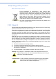
Définitions AVERTISSEMENT! Une déclaration AVERTISSEMENT fournit des informations importantes sur une situation potentiellement dangereuse qui, si elle n'est pas évitée, pourrait entraîner la mort ou des blessures graves. ATTENTION! Une déclaration CAUTION fournit des informations importantes sur une situation potentiellement dangereuse qui, si elle n'est pas évitée, peut entraîner des blessures mineures ou modérées à l'utilisateur ou au patient ou des dommages à l'équipement ou à d'autres biens.
5. Débranchez cet équipement de la prise d’alimentation avant de le nettoyer. Utilisez un chiffon humide. N’utilisez pas de détergent liquide ou en aérosol pour nettoyer cet équipement et gardez-le loin de l’humidité. ATTENTION! Afin d'éviter les courts-circuits et, conséquemment, endommager l'appareil, évitez que des liquides de viennent en contact avec l'appareil.
Avertissement! L’utilisation de cet appareil n’est pas recommandée en présence de mélange de vapeurs anesthésiques inflammable avec de l’air, de l’oxygène, de l’oxyde nitreux ni avec les systèmes d’entretien de la vie. 11. Protection de l’environnement: suivez les exigences nationales en matière de l’élimination de cet appareil. 12. Entretien: pour entretenir et nettoyer les surfaces adéquatement, utilisez uniquement des produits approuvés ou nettoyez à sec.
18. Utilisez un cordon d’alimentation homologué de calibre correspondant à la tension du secteur et qui est conforme aux normes de sécurité propres à votre pays. Protection de l’environnement Suivez les exigences nationales en matière de l’élimination de cet appareil. 19. AVERTISSEMENT – Ne modifiez pas cet équipement sans l’autorisation du fabricant. 20. AVERTISSEMENT – Afin d’éviter le risque de décharges électriques, cet équipement doit être branché à une prise d’alimentation équipée d’une mise à terre.
Disposing of the product Within the European Union EU-wide legislation, as implemented in each member state, requires that waste electrical and electronic products carrying the mark (left) must be disposed of separately from normal household waste. This includes monitors and electrical accessories, such as signal cables or power cords. When you need to dispose of your display products, please follow the guidance of your local authority, or ask the shop where you purchased the product.
List of Accessories Before installing your Point of Care Terminal, ensure that the following materials have been received: POC-621 SERIES Point-of-Care Terminal Mounting kits and a packet of screws 1 x VESA mounting note 1 x China RoHs note Warning! No user serviceable parts inside, refer servicing to qualified personnel. Only the accessories indicated on the list of accessories above have been tested and approved to be used with the device.
Additional Information and Assistance Contact your distributor, sales representative, or Advantech's customer service center for technical support if you need additional assistance. Please have the following information ready before you call: Product name and serial number Description of your peripheral attachments Description of your software (operating system, version, application software, etc.
Contents Chapter Chapter 1 General Information ............................1 1.1 1.2 1.3 1.4 1.5 1.6 Introduction ............................................................................................... 2 Specifications ............................................................................................ 2 Dimensions ............................................................................................... 5 Figure 1.1 Dimensions of the POC-621.......................................
3.6 Battery Operation Sequence................................................................... 33 4 Operation and Safety........................ 35 4.1 4.2 4.3 4.4 4.5 4.6 4.7 4.8 4.9 General Safety Guide ............................................................................. 36 Thermal Dissipation ................................................................................ 36 Disconnect the Power .............................................................................
Chapter 1 1 General Information
1.1 Introduction Advantech POC-621 is a multimedia Intel® Core™ i7/i5/Celeron processor solution designed for mobile computing as a Point-of-Care terminal (POC). It is a PC-based system with 21.5" wide screen TFT LCD display, HDMI out, dual on-board 10/100/ 1000 PCIE Ethernet controllers, and 1 x LAN port. It supports Intel AMT11 functions. It has 2 x COM ports, 4 x USB 2.0 ports, and 1 x 24-bit stereo audio controller. With an optional 2.5" SATA drive, POC-621 is a user-friendly computer.
USB 2.0 Type A I/O Ports 2 x (USB 3.2 Gen 2) 1 x (with display function via USB type C alternative mode) 4x Mic in/ Headphone 1/1 out LAN isolation, 2x 1.5KV 1x Serial Ports 2 x RS-232(isolated 1.5KV) serial port DCIN Default 18V DC IN Power Input DC/AC DC model: 18V, max. 100W/AC model: 100 ~ 240V, max.
Operating System Windows 10 IoT Ent (64 bits only), Linux (support by request) Memory Up to 32GB DDR4 SODIMM x 2 Primary Storage NVME SSD 128/ 256G/ 512GB or 1TB (M.2 2280, PCIe Interface) Secondary Storage 1 x 2.5" SATA SSD(2nd storage) optional Intel Wireless-AC9260 or Intel Dual Band WirelessWLAN AC 8265 Bluetooth Optional Configuration RFID Smart Card Backup Battery Hot swapping Battery module Camera TPM 1.2/2.0 Touch Panel POC-621 Series User Manual 5.1/ 4.
Chapter 1 1.3 Dimensions Dimensions: 523 x 356 x 62 mm; 20 x 14 x 2.44 in General Information Figure 1.1 Dimensions of the POC-621 Figure 1.
Figure 1.3 POC-621 with Smart Card Reader Dimensions Figure 1.
Chapter 1 VESA Mounting: 75 x 75 mm; 100 x 100 mm; 3.93 x 3.93 in, 2.9 x 2.9 in Mounting screws: M4, 0.7pitch, 10mm long Warning! Use suitable mounting apparatus to avoid risk of injury.
1.3.1 Optional Modules Memory: Up to 32GB DDR4 SODIMM x 2 Primary Storage: NVME (M2 2280, PCIe Interface) 2.5" SATA SSD Wi-Fi and Bluetooth module: Intel Wireless-AC9260, Intel Dual Band WirelessAC 8265 RFID module: RFIDEAS OEM-7522AXU Smart Card Li-ion Battery 8400mAh 10.8V 190.
1.4 Operating Principle The device provides input through a touch panel & hard keys located on its bottom. It provides input for accessories via USB ports or its LAN/WLAN connections. The device computes the input data with its processing unit and then outputs the generated data to an LCD panel, accessories, or other devices through its I/O ports or through its LAN/WLAN connections. This device is able to store data in its storage.
– Mild reading vision impairment or vision corrected to log MAR 0,2 (6/10 or 20/ 32) – One arm / hand system capable of guiding and holding device – Average degree of aging-related short term memory impairment – impaired by 40% resulting in 60% of normal hearing at 500 Hz to 2 kHz 1.
Chapter 1 General Information 11 POC-621 Series User Manual
POC-621 Series User Manual 12
Chapter 2 System Setup 2
2.1 A Quick Tour of the POC-621 Series Before you start to set up the POC-621 take a moment to become familiar with the locations and purposes of the controls, drives, connection, and ports. These are illustrated in the figures below. When you place the POC-621 Series upright on the desktop, its front panel appears as shown in the following figure — Figure 2.1. 2.1.1 Front view (2) (1) Figure 2.
Chapter 2 Figure 2.4 Rear View of Multi I/O ports (DC-in model) Note! The equipotential terminal needs to be connected to a ground in the hospital before system boot to protect the operator and the system. 15 POC-621 Series User Manual System Setup Figure 2.
2.2 Installation Procedures 2.2.1 Connecting the Power Cord (DC model) The POC-621 can only be powered by a DC adapter (SINPRO Model no.HPU101107). Be sure to always handle the power cords by holding the plug ends only. Follow these procedures in the correct order: 1. Connect the female end of the power cord to the AC Adapter. 2. Connect the 3-pin male plug of the power cord to an electrical outlet. Figure 2.5 Connecting the Power Cord 2.2.
The POC-621-01 SERIES can only be powered by AC internal power (FSP Model no. FSP150M-K24-18). Be sure to always handle the power cords by holding the plug ends only. Follow these procedures in order: 1. Connect the female end of the power cord to AC in. 2. Connect the 3-pin male plug of the power cord to an electrical outlet. Chapter 2 2.2.3 Connecting the ACIN System Setup 2.2.4 Connecting the Ground pin 1. System ready and find the Equipotential Terminal on rear side of POC.
2. Prepare the grounding cable and the other terminal link to hospital ground/earth system. Figure 2.7 Grounding Cable with Connector 3. Grounding cable plug with POC-621 Equipotential Terminal (See Figure 2.7) 2.3 Running the BIOS Setup Program Your POC-621 was probably set up and configured by your dealer prior to delivery.
Recent releases of operating systems from major vendors include setup programs which load automatically and guide you through hard disk preparation and operating system installation. The guidelines below will help you determine the steps necessary to installing your operating system on the panel PC hard drive. Note! Some distributors and system integrators may have already preinstalled system software prior to shipment of your panel PC. 2.
2.6 Troubleshooting The following details events in which the system behaves abnormally In such cases, please refer to the troubleshooting instructions below. 2.6.1 POC not Power ON. Press the power button but no power on (Power ON Green indicator is still off) Please check 1. Check that adapter/DCIN is plugged in properly. 2. Check that the adapter/DCIN is plugged in to the correct direction to POC DCIN Connector 3. Check that the AC power cord plug and adapter are correct 4.
POC display shows a black background and some words. 1. Check that the Windows OS is installed properly. 2. Check that the BIOS boot order is set properly. Please setup the BIOS boot device using the following procedure: a) Press the “Del” key at power up, into the BIOS Menu. b) In Boot – Boot Option #1 – Select “Windows Boot Manager (Storage name) c) In Save & Exit – Save Changes and Reset – Select Yes d) POC system will reset and boot up.
2.7 EMC Declaration Guidance and manufacturer’s declaration – electromagnetic emissions The model POC-621 SERIES is intended for use in an electromagnetic environment as specified below. The customer or the user of the POC-621 SERIES should assure that it is used in such an environment. Compliance Electromagnetic environment – guidance RF emissions CISPR 11 Group 1 The model POC-621 Series uses RF energy only for its internal function.
POC-621 SERIES is intended for use in the electromagnetic environment specified below. The customer or the user of the model POC-621 SERIES should assure that it is used in such an environment. Compliance level Electromagnetic environment –guidance 8 kV contact 15 kV air 8 kV contact 15 kV air Floors should be wood, concrete or ceramic tile. If floors are covered with synthetic material, the relative humidity should be at least 30%.
Guidance and manufacturer’s declaration – electromagnetic immunity The model POC-621 SERIES is intended for use in the electromagnetic environment specified below. The customer or the user of the model POC-621 SERIES should assure that it is used in such an environment.
25 POC-621 Series User Manual System Setup Field strengths from fixed transmitters, such as base stations for radio (cellular/cordless) telephones and land mobile radios, amateur radio, AM and FM radio broadcast and TV broadcast cannot be predicted theoretically with accuracy. To assess the electromagnetic environment due to fixed RF transmitters, an electromagnetic site survey should be considered.
POC-621 Series User Manual 26
Chapter 3 3 Hot Swapping Battery Pack Operation
POC supports hot swapping battery pack options. This hot swapping battery pack could hotplug install two battery packs. This chapter describes how to install a battery and its operation. 3.1 Installing Hot Swappable Battery Packs 1. Open the battery door: Users can access the battery slot using the arrowhead buttons (circled in red below). 1) Press the arrowhead button. 2) Pull open the door to access the battery slot.
ATTENTION! Nous recommandons de tenir la batterie à deux mains lors de l'insertion dans le système d'alimentation POC-BAT-201-62. Caution! Please hold the battery with both hands when installing the battery into the slot of the backpack. ATTENTION! Veuillez tenir la batterie à deux mains lors de l'installation de la batterie dans la fente du sac à dos. 29 POC-621 Series User Manual Hot Swapping Battery Pack Operation 2.
3. Close the battery door. When the door is closed to the end, a “click” will be heard to ensure that the door closes properly. Warning! Without close the battery door may cause the battery to drop out. AVERTISSEMENT! Si vous ne fermez pas le couvercle de la batterie, la batterie risque de tomber. Caution! Lay the pull ring and mylar (indicated in the image below) flat in their original position before closing the door.
Battery pack charge capacity indicator. Press the below red circle button, and the battery pack will turn on the indicator to show its capacity percentage. The illuminated LED represents the battery capacity. 31 POC-621 Series User Manual Hot Swapping Battery Pack Operation 3.
3.3 Hot Swapping Battery Pack Battery Capacity Indicator and Windows Battery Information 1. Hot swapping battery pack capacity indicator The Hot swapping battery pack features an LED indicator that shows each battery charge capacity percentage. In Discharge mode, the indicator shows the following capacity. Battery Capacity LED 0~10% 11~20% 21~50% 51~100% Flash 1 LED (0.5Hz Frequency) 1 LED ON 2 LED ON 3 LED ON In Charge mode, the indicator shows the following capacity.
Battery remain capacity כ100% Battery full capacity Chapter 3 Windows will assess each batteries’ capacity (unit: mAh) to calculate the capacity percentage. Install single battery capacity percentage = Install dual battery average capacity percentage = 3.4 Regular use of Battery Pack Below are instructions for maintaining a healthy battery: 1. Always fully charge new batteries before first use. 2.
POC-621 Series User Manual 34
Chapter 4 4 Operation and Safety
4.1 General Safety Guide For your own safety and that of your equipment, always take the following precautions.
Unplugging the power cord is the only way to disconnect power completely. Make sure at least one end of the power cord is within easy reach so that you can unplug the computer when you need to. Avertissement! Votre cordon d'alimentation est équipé d'une fiche de mise à la terre à trois fils (une fiche qui a une troisième broche de mise à la terre). Cette fiche s'adapte uniquement à une prise secteur mise à la terre.
4.4 Proper Handling Handle your POC system with care. The system is made of metal, glass, and plastic; and contains sensitive electronic components. POC systems are heavy and require two hands during handling. Hold the battery pack with both hands when installing, removing, or replacing it. Warning! Do not attempt to use the POC system if it is damaged (for example, the case is cracked or broken) as this may cause injury. Caution! 1) Setup and install POC system on a stable work surface.
2. 4.6 Battery Safety Instruction 1. The POC-621 system should only be powered by an Advantech battery pack or compatible battery pack supplied by Advantech. Warning! 1) Do not insert non-Advantech battery packs into the POC-621 system. 2) Do not attempt to use battery packs from a different brand or thirdparty. AVERTISSEMENT! 1) N'insérez pas de blocs-batteries non Advantech dans le système POC-621. 2) N'essayez pas d'utiliser des batteries d'une marque différente. 2.
AVERTISSEMENT! L'utilisation d'un chargeur de batterie d'une marque différente peut entraîner la exploser et provoquer un incendie. 4. Do not short the battery pack connector using metal or a wire lead. Warning! Wire lead shorts can cause the battery to explode and result in fire. AVERTISSEMENT! Les courts-circuits du fil peuvent provoquer l'explosion de la batterie et provoquer un incendie. 5. Do not drop the battery pack.
Do not penetrate the battery with nails, strike the battery with a hammer, step on the battery, or otherwise subject it to significant impact or shock. Warning! Batteries are at risk of exploding and may cause fire if subjected to significant impact. 8. 9. Do not expose the battery pack to moisture or water. Do not disassemble or modify the battery pack. The battery pack contains safety and protection circuits that if damaged, may cause the battery to overheat, explode, or ignite.
13. Do not discharge the battery pack using any device other than the POC-621 system or a device specified by Advantech. Warning! Using the battery pack to power devices other than the POC-621 system may damage the battery, limit performance, or reduce the battery life capacity. Additionally, exposure to abnormal current may cause the battery pack to overheat, explode, or ignite, causing serious injury.
Caution! When the time between charges decreases significantly, check the voltage of the battery pack before charging. If the battery performance drop significantly, please do not use this battery pack. 4.7 Emergency Scenarios If you notice any of the following, stop charging or using the battery immediately: 1. The battery has become swollen, bulged, or deformed. 2. The battery is leaking fluid, smoke, or a foul odor. 3. The battery temperature is extremely hot. 4.
4.8 Battery Storage and Transportation 1. 2. 3. 4. 5. Store the battery in a dry environment with a room temperature of 0 ~ 25 °C (32 ~ 77 °F) for optimum health. Do not expose the battery pack to direct sunlight (heat) or store the battery pack inside vehicles in hot weather for extended periods of time. When transporting or temporarily storing the battery in a vehicle, the internal vehicle temperature should not be greater than -20 °C (-4 °F) but no more than 50 °C (122 °F).
When the battery pack has reached the end of its service life, do not use general household waste for disposal. Follow local laws and government regulations for correct battery disposal. Caution! Cover terminals with tape to prevent inadvertent contact with other batteries or metal objects. 2. To reduce the risk of fire or burns, do not disassemble, crush, puncture, expose to fire or water, or short the battery’s external contacts. Used batteries may still have a partial charge.
POC-621 Series User Manual 46
Appendix A A POC-621 Series VESA Mounting
A.1 Install VESA Mounting The POC-621 supports standards VESA mounting to help system integrators conveniently integrate the panel PC into their system. Never use mounting brackets except as provided by Advantech to prevent unreliable mounting of the POC-621. VESA mount installation should be carried out by a professional technician; please contact a service technician or your retailer if you need this service. Installation instructions follow: 1. First attach the wall-mount to the heat-sink of the POC-62.
Appendix B B Driver Installation
B.1 Driver Installation The POC system supports Windows is WIN10 IoT/RS5 version or later, 64 bits only. It no longer supports 32 bits drivers. Warning! Please use a clean OS to install the driver, otherwise, it might cause an unexpected error. Windows Driver List: Please follow your OS version to install the proper driver. Please follow the sequence below to install drivers. Install sequence Folder Name Note 1 Chipset 2 Graphics Please install chipset driver first.
Appendix C C PCM-8722 Connector Map
C.
53 POC-621 Series User Manual Appendix C PCM-8722 Connector Map
POC-621 Series User Manual 54
Appendix D D PCM-8722 Jumper Settings
D.1 PCM-8722 Jumper setting The POC system uses PCM-8722 PCBA.
Appendix D PCM-8722 Jumper Settings Table D.1: CN3 ME Manufacturing Mode Description Setting (1-2) (No Connect) ME Manufacturing Mode Function ME Manufacturing Mode Normal Operation (Default) Table D.2: CN5 Clear CMOS Description Setting (1-2) (No Connect) Clear CMOS Setup Function Clear CMOS Setup Normal Operation (Default) Table D.3: CN6 (Not Install) Clear ME Description Setting (1-2) (No Connect) Clear ME Setup Function Clear ME Setup Normal Operation (Default) Table D.
Table D.5: CN13 LVDS Voltage Setup Description Setting (1-2) (2-3) Select panel LVDS voltage setting Function Panel LVDS voltage 5V (Default) Panel LVDS voltage 3.3V Table D.6: CN40 Power Button (Internal Test Only) Description Setting (Pin 2) (No Connect) Power Button Signal Function Short pin 1 to Power ON system Normal Operation (Default) Table D.7: PCN4 Power Debug (Reserved) Description Setting (No Connect) Power Debug, Internal Test Only Function Normal Operation (Default) Table D.
SW1 Pin 2 SW1 Pin 3 Board Configuration Hi (OFF) Hi (OFF) Hi (OFF) Hi (OFF) Low (ON) Low (ON) Low (ON) Low (ON) Hi (OFF) Hi (OFF) Low (ON) Hi (OFF) Hi (OFF) Hi (OFF) Low (ON) Hi (OFF) Hi (OFF) Low (ON) Hi (OFF) Hi (OFF) Hi (OFF) Low (ON) Hi (OFF) Hi (OFF) Board Config. 1 (Default) Board Config. 2 Board Config. 3 Board Config. 4 Board Config. 5 Board Config. 6 Board Config. 7 Board Config. 8 Table D.
POC-621 System setting POC-621, with audio board, 5V LVDS Panel SW1 Pin 1 SW1 Pin 2 SW1 Pin 3 SW1 Pin 4 SW2 Pin 1 SW2 Pin 2 SW2 Pin 3 SW2 Pin 4 CN13 Hi(OFF) Hi(OFF) POC-621 Series User Manual Hi(OFF) Hi(OFF) Low(ON) 60 Hi(OFF) Hi(OFF) Hi(OFF) (1-2)
Appendix E Advanced BIOS Functions E
E.1 Advanced BIOS Functions This appendix introduces the POC systems advanced function via the BIOS menu. 1. Power Button Function Enable/Disable You can enable/disable the power button function in the BIOS menu. If you disable the power button in S0 (System ON) status, the power button will not work. Therefore, users cannot turn off the system using the power button. Users need to use software to turn the system off.
BIOS Menu location: BIOS Menu – Advanced – IT5121 HW Monitor – touch button control Enable: Front bezel touch button control function work. (Default) Disable: Front bezel touch button control function not work. 5. Read light Button Control You can enable/disable read light button function in BIOS menu. If you disable the read light button, this button will not work. So the user cannot turn on read light by this button. The read light function will always off.
www.advantech.com Please verify specifications before quoting. This guide is intended for reference purposes only. All product specifications are subject to change without notice. No part of this publication may be reproduced in any form or by any means, electronic, photocopying, recording or otherwise, without prior written permission from the publisher. All brand and product names are trademarks or registered trademarks of their respective companies. © Advantech Co., Ltd.