
Product Info


LT103OEM UWB Radar Module
Rev.2.1 Pag. 10 of 14
Bootloader (optional)
The module may be provided with a bootloader application. This feature enables the on-
field reprogramming of the module but require an additional start-up sequence in order to
run the application FW (see protocol documentation).
This feature is provided on demand.
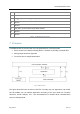
8 Typical Schematic
The typical schematic for LT103OEM is reported in Fig. 4.
Fig. 7 Typical Schematic
A LDO may be used instead of DC/DC converter. The maximum ripple for the DC/DC output
is 25mV.
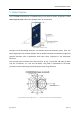
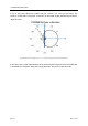
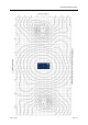
9 Suggested layout
It is strongly recommended to follow the following layout for your board carrying the
LT103OEM. Different layouts may result in slight reductions in performances. Reference
layout files in Gerber format for host board is available on demand.