
User Manual


Filac
™
3000 EZ/EZA Electronic Thermometer
4
Table of Contents
V. Instructions For Use
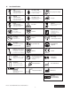
Probe Covers —Applying & Removing
1. Open probe cover box by lifting tab at top corner and pulling to remove toppanel.
2. Insert box of probe covers into top of isolation chamber. (To aid infection control,
never switch boxes between blue and red isolation chambers. Also, never switch
probes between blue and red isolation chambers. Keep like colors together.)
3. Remove probe from the probe well. This automatically turns on thethermometer.
4. To help remind the user to apply or remove a probe cover, a probe icon with
flashing probe cover will be displayed when the probe is withdrawn from the
probe well and following a completed temperature measurement.
5. Insert the probe end into a cover in the box. Push the handle firmly until you feel
the cover “snap” into place.
6. Take appropriate temperature measurement (oral, axillary or rectal).
7. Eject the used cover into bio-waste container by pressing top button.
8. Remove, discard and replace box when empty.
Changing Isolation Chambers
and Probes
1. For aiding in infection control, use only the Blue probe and Blue isolation chamber
for Oral and Axillary temperature taking. The Red probe and Red isolation
chamber must only be used for Rectal temperature taking.
2. Do not attach a Red probe to a Blue isolation chamber or vice-versa.
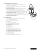
3. To remove or replace any isolation chamber/probe assembly, grasp the isolation
chamber from each side as shown.
4. Squeeze inward releasing the snaps and slide the isolation chamber up topull off.
5. To replace, align probe well finger with opening in the top of the unit.
6. Slide the isolation chamber down until the side snaps “click” into place.
7. The probe is connected to the thermometer automatically.
8. To change probes, remove the isolation chamber as described previously.
9. Grasp the sides of the L-shaped
connector piece with one hand
and then using other hand pull
backward on the latch holding
the end of the
L-shapedconnector.
10. Once free of the latch, slide the
L-shaped connector out of
isolationchamber.
11. To replace, properly align the
top of the L-shaped connector
to the slot on the back of the
isolation chamber.
12. Then slide the connector up
into the slot pressing firmly on
the bottom of the connector
until it “clicks” intoplace.